Pouring stream protecting device for pouring molten steel through large ladle in continuous casting

A technology for pouring molten steel and protection devices, which is applied in casting equipment, casting molten material containers, metal processing equipment, etc., can solve the problems of poor protection effects, etc., and achieve outstanding effects, strong operability, and use effects

Inactive Publication Date: 2016-03-16
SHANDONG IRON & STEEL CO LTD
View PDF8 Cites 4 Cited by
  • Summary
  • Abstract
  • Description
  • Claims
  • Application Information

AI Technical Summary

Benefits of technology

This patented method improves upon traditional methods for protective lining used during casting operations by introducing a new type of liquid metal flow system called injector channels or triple stages into the main body of the vessel's refractory material (tank). These systems include interfaces like a narrower pipe section at one end, wider tubes near another end, and even more pipelines within it. By inserting this device between different parts of the tank, there are several technical improvements: improved safety measures due to reduced risk from overheated castings caused by high levels of heat; easier installations compared to previous designs without any modifications needed beforehand; stronger performance than current solutions such as immersion liners when installed under these conditions.

Problems solved by technology

This patented technical solution described in the current method involves opening up an entire cast iron line without any interruptions or shutdown periods during each operation. However, there are potential safety concerns due to possible contamination caused by metal splashes on other components such as equipment used in the coolant system.

Method used


Image

  • Pouring stream protecting device for pouring molten steel through large ladle in continuous casting
  • Pouring stream protecting device for pouring molten steel through large ladle in continuous casting

Examples


Embodiment Construction

[0021] The present invention will be described in further detail below in conjunction with the accompanying drawings and specific embodiments.

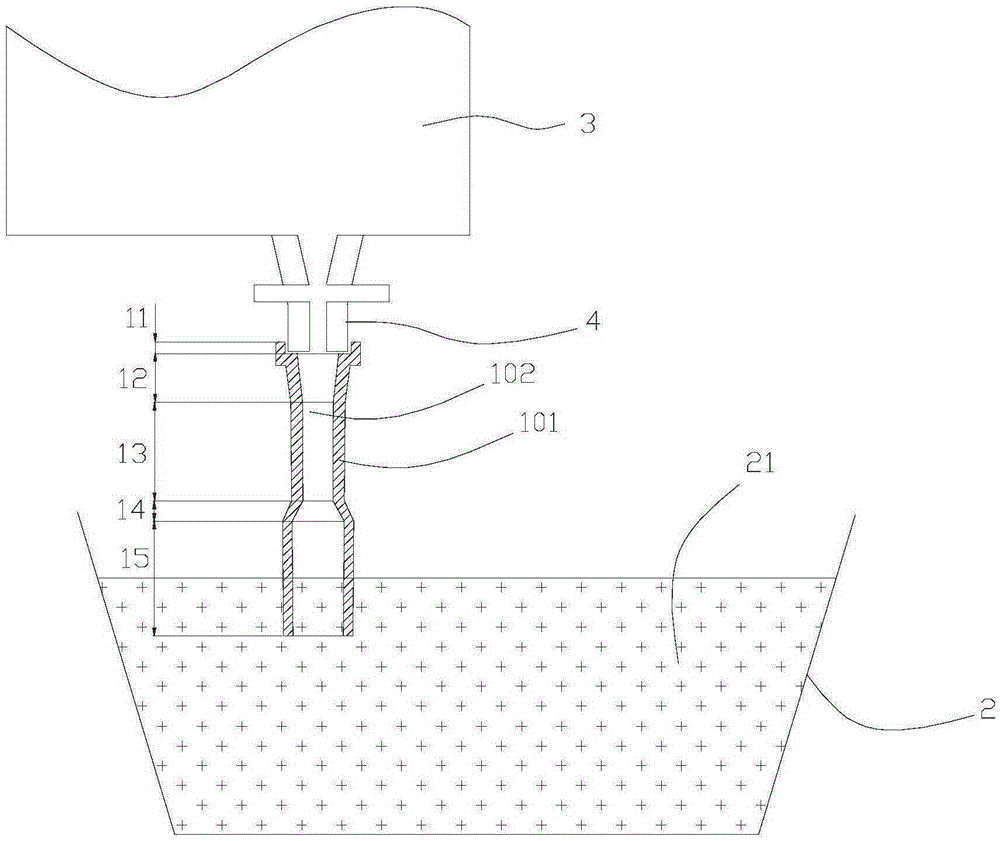
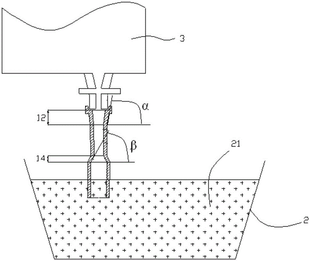
[0022] In order to describe the structure and application of this embodiment more clearly, figure 1 and figure 2 It shows this embodiment and its connection relationship and positional relationship with the big bag 3 and the middle bag 2 . At the bottom of the bale 3, there is a water inlet 4 for the bale.

[0023] Such as figure 1 and figure 2 As shown, this embodiment includes a casing 101 and a channel 102 located inside the casing 101 and penetrating the casing 101 in the axial direction of the casing 101 for passing drainage sand and molten steel. Preferably, the casing 101 is cylindrical as a whole, has substantially equal wall thickness, and has a trumpet-like appearance. The channel 102 in the housing 101 includes: an interface portion 11 , a neck portion 12 , a narrow straight portion 13 , a tapered portion 14 , and a wid


PUM

PropertyMeasurementUnit
Cone angleaaaaaaaaaa
Lengthaaaaaaaaaa

Abstract

The invention provides a pouring stream protecting device for pouring molten steel through a large ladle in continuous casting. The pouring stream protecting device comprises a shell and a channel, wherein the channel is located in the shell and penetrates through the shell, and ladle filler sand and the molten steel can pass through the channel. The channel comprises a connector part, a narrow straight barrel part and a wide straight barrel part, wherein the connector part is used for being matched with an upper nozzle of the large ladle for sealing, and the upper nozzle of the large ladle is sleeved with the connector part; one end of the narrow straight barrel part is communicated with the connector part, and the inner diameter of the narrow straight barrel part is smaller than that of the connector part; the wide straight barrel part is communicated with the other end of the narrow straight barrel part, and the inner diameter of the wide straight barrel part is larger than that of the narrow straight barrel part. Through the pouring stream protecting device, the nature of large-ladle pouring protection can be improved, and the large-ladle pouring protection effect is prominent; besides, the pouring stream protecting device is easy to mount, convenient to use and high in operability.

Description


Claims


Application Information

Patent Timeline
Owner SHANDONG IRON & STEEL CO LTD
Why Eureka
Try Eureka