Application of positioning rib in large storage tank bearing platform ring wall foundation

A large-scale storage tank and positioning rib technology, which is applied in the field of invention and application, can solve the problems of excessive flatness of the surface of the surrounding wall, waste of construction period and construction cost, difficulty in finishing the surface of the surrounding wall, etc., so as to shorten the construction period, improve the flatness, reduce the The effect of construction costs

Active Publication Date: 2016-03-30
SINOCHEM ZHOUSHAN XINGHAI CONSTR
View PDF5 Cites 0 Cited by
  • Summary
  • Abstract
  • Description
  • Claims
  • Application Information

AI Technical Summary

Problems solved by technology

[0002] At present, in the construction of the ring wall of storage tanks in large-scale petrochemical projects, the method of elevation measurement and manual leveling is mostly used to control the surface smoothness of the ring wall. Since there is no fixed reference for the repair personne

Method used


Image

  • Application of positioning rib in large storage tank bearing platform ring wall foundation

Examples


Embodiment Construction

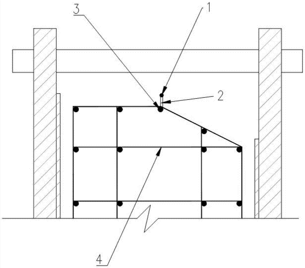
[0012] Such as figure 1 As shown, the inventive application of the positioning rib of the present invention in the foundation of the ring wall of the large-scale storage tank cap, the positioning rib is applied to the foundation of the ring wall of the large-scale storage tank cap, and the elevation of the positioning rib is the same as that of the ring wall foundation after forming Consistent, the positioning rib is an annular ring-shaped steel bar 1 arranged in the horizontal direction, the bottom end of the ring-shaped steel bar 1 is connected to the top of a plurality of vertical bars 2 by welding, and the adjacent vertical bars 2 The distance between them is 900-1100mm, and the bottom end of each vertical bar 2 is welded and connected with the main bar 3 arranged along the horizontal direction, and the main bar 3 is welded and fixed on the top of the reinforced grid frame 4 of the ring wall foundation of the storage tank cap.

[0013] As a further improvement of the present


PUM


Abstract

The invention provides an application of a positioning rib in a large storage tank bearing platform ring wall foundation. By means of the application, the flatness of the surface of a formed ring wall is improved, trimming of the surface of the ring wall is more convenient, efficient and rapid, the construction period is shortened, and the construction cost is reduced. The positioning rib is applied in the large storage tank bearing platform ring wall foundation, the elevation of the positioning rib and the elevation of the formed ring wall foundation are consistent, the positioning rib is an annular steel bar (1) arranged in the horizontal direction, the bottom end of the annular steel bar (1) is welded to the top ends of vertical ribs (2) arranged vertically, and the distance between every two adjacent vertical ribs (2) is 900-1100 mm. The bottom end of each vertical rib (2) is welded to a main rib (3) arranged in the horizontal direction, and the main ribs (3) are welded and fixed to the top of a storage tank bearing platform ring wall foundation steel bar net frame (4).

Description


Claims


Application Information

Patent Timeline
Owner SINOCHEM ZHOUSHAN XINGHAI CONSTR
Why Eureka
Try Eureka