Automatic transmission gear-shifting control method used under working condition of misoperation

A technology of automatic transmission and control method, applied in transmission control, components with teeth, belts/chains/gears, etc., can solve problems affecting driving experience, etc., to avoid excessive temperature rise, reduce wear, and reduce comfortable effect

Active Publication Date: 2016-04-06
SHANGHAI AUTOMOBILE GEAR WORKS
View PDF5 Cites 1 Cited by
  • Summary
  • Abstract
  • Description
  • Claims
  • Application Information

AI Technical Summary

Benefits of technology

The technical effect of this new technology described in this patented text allows for accurate detection of any errors or deviations during operation without causing discomfort when changing between different transmission ratios. This means it will help prevent damage from overheated friction plates used on these systems while still being able to smoothly shift through various speeds.

Problems solved by technology

This patented technical problem addressed by this patents relates to improving the performance of automated transmission systems while reducing their impact upon human drivers caused by changes made overtime through acceleration/deceleration movements.

Method used


Image

  • Automatic transmission gear-shifting control method used under working condition of misoperation

Examples


Embodiment 1

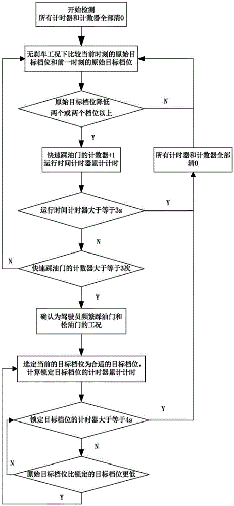
[0019] like figure 1 As shown, taking a car equipped with a 6-speed automatic transmission as an example, this embodiment includes the following steps:

[0020] Step 1. Set the running time timer and clear the quick accelerator pedal counter.

[0021] Step 2. Under the no-braking condition, compare the target gear at the current moment with the original target gear at the previous moment to determine whether a misoperation condition occurs.

[0022] The target gear at the current moment and the original target gear at the previous moment are obtained through the shift pattern diagram.

[0023] The misoperation condition refers to: within the judgment time limit, it is detected that the number of times the driver steps on the accelerator for multiple times is greater than or equal to the preset threshold of the number of times of stepping on the accelerator, and the gear difference before and after each step on the accelerator is greater than or equal to The preset gear differen


PUM


Abstract

An automatic transmission gear-shifting control method used under the working condition of misoperation comprises the steps that whether the working condition of misoperation exists or not is judged under the braking-free working condition in real time, namely the detected frequent accelerator stepping times exceeds a preset accelerator stepping time threshold within a judgment time limit, and it is satisfied that the gear difference before and after an accelerator stepping action occurs each time exceeds a preset gear difference threshold; a transmission can optimize gears under the working condition of misoperation within a locking time to assist driving. By the adoption of the automatic transmission gear-shifting control method, abrasion of a synchronizer and a clutch can be effectively decreased, and too quick temperature rise of the clutch is avoided to reduce the discomfort possibly brought by frequent gear shifting.

Description


Claims


Application Information

Patent Timeline
Owner SHANGHAI AUTOMOBILE GEAR WORKS
Why Eureka
Try Eureka