Special-shaped shielding device

A shielding device and special-shaped technology, applied in the direction of magnetic/electric field shielding, electrical components, etc., can solve the problems of difficulty in shielding and installation, and achieve the effects of reducing man-hours, improving efficiency, and simple structure

Inactive Publication Date: 2016-05-04
CHINA ELECTRIC POWER RES INST +3
View PDF0 Cites 1 Cited by
  • Summary
  • Abstract
  • Description
  • Claims
  • Application Information

AI Technical Summary

Benefits of technology

This patented technology solves problems with reducing interference between different types of electronic devices by creating an electrostatic screen that prevents them from being affected when they are used at high voltages. It also simplifies its construction process for easy installment without requiring complicated tools like wires. Overall this makes it more efficient than traditional methods such as grounded metal plates.

Problems solved by technology

The technical problem addressed in this patented text relates to reducing coronal phenomenon caused by high voltages during use for transmitting signals over long distances without causing damage from lightning strikes that can occur at lower levels than usual.

Method used


Image

  • Special-shaped shielding device
  • Special-shaped shielding device
  • Special-shaped shielding device

Examples


Embodiment Construction

[0018] The present invention will be specifically described below in conjunction with the accompanying drawings and embodiments.

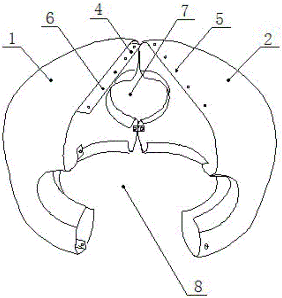
[0019] figure 1 Shown is the structural representation of the present invention.

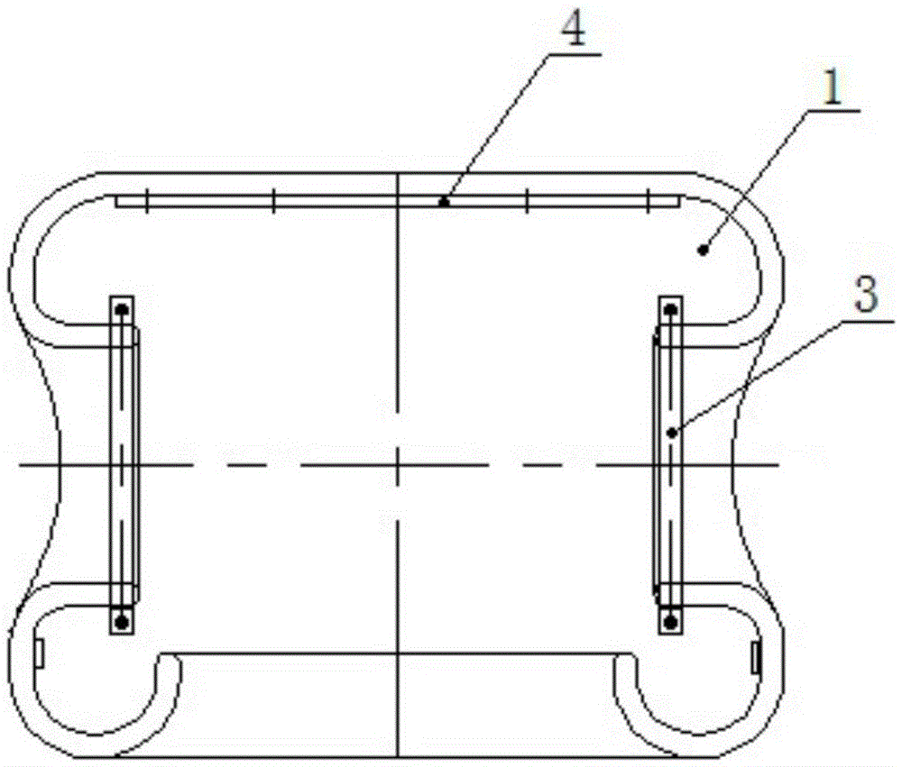
[0020] Figure 4 Shown is a schematic cross-sectional view of the combined assembly of the present invention.

[0021] The present invention includes a left shielding body 1 , a right shielding body 2 and a clip 3 .

[0022] The left shielding body 1 and the right shielding body 2 are both hollow irregular hemispherical as a whole, and they are hollow irregular spheres after fastening. The two sides of the sphere are provided with conductive rod through holes 7 with inwardly curved surfaces. An operating hole 8 with an inwardly curved surface is provided.

[0023] Clamps 3 are provided on the edges of the through holes 7 of the conductive rods on both sides, and the left shield 1 and the right shield 2 are connected to the conductive rods through the clamps 3 .

[


PUM


Abstract

The invention discloses a special-shaped shielding device, which comprises a left shielding body, a right shielding body and clamps, wherein the left shielding body and the right shielding body are in a hollow irregular hemi-spherical shape on the whole, and form a hollow irregular sphere after being fastened; conducting rod through holes of inflected arc-shaped surfaces are arranged at two sides of the sphere; operation holes of the inflected arc shaped surfaces are arranged at the bottom part of the sphere; the clamps are arranged on the edges of the conducting rod through holes at two sides; and the left shielding body and the right shielding body are connected with a conducting rod through the clamps. The special-shaped shielding device can effectively solve the shielding problem of a three-dimensional or multi-dimensional electric field of AC/DC extra-high voltage electrical equipment, is simple in structure and convenient to install and dismantle, and working hours are greatly reduced and the efficiency is improved.

Description


Claims


Application Information

Patent Timeline
Owner CHINA ELECTRIC POWER RES INST
Why Eureka
Try Eureka