Pushing device of reagent detection strips and full-automatic detection equipment with pushing device

A technology of pushing device and test strip, applied in the direction of analysis materials, instruments, etc., can solve problems such as affecting test results, secondary pollution of reagent test strips, etc., so as to improve operation efficiency, improve accuracy, and improve the accuracy of test results. Effect

Active Publication Date: 2016-06-08
深圳市汇研科创生物科技有限公司
View PDF6 Cites 1 Cited by
  • Summary
  • Abstract
  • Description
  • Claims
  • Application Information

AI Technical Summary

Problems solved by technology

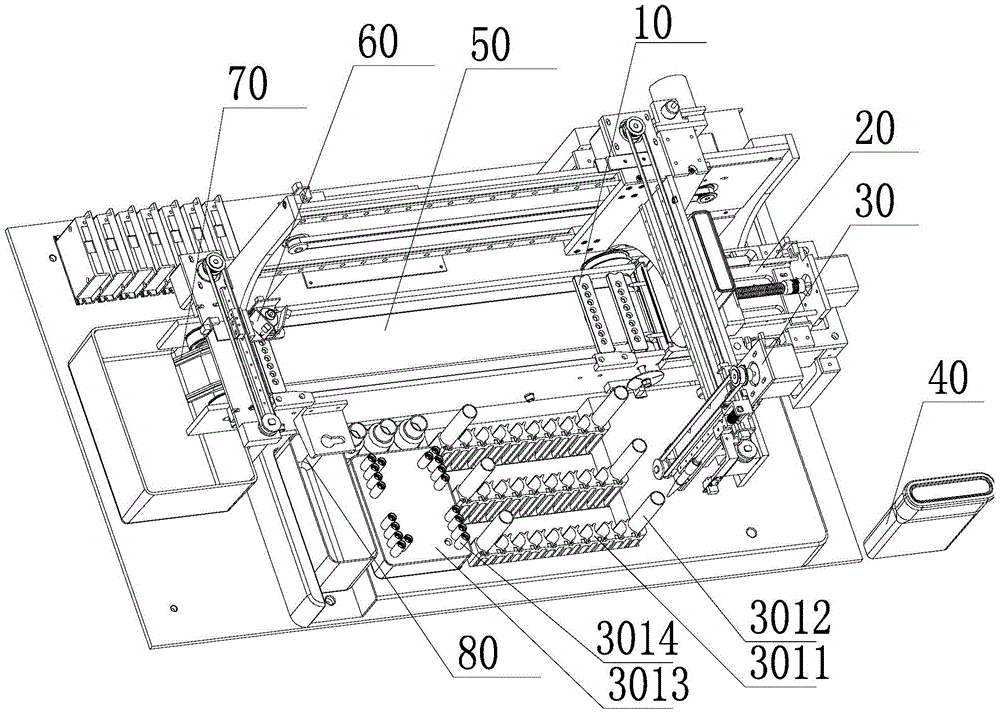
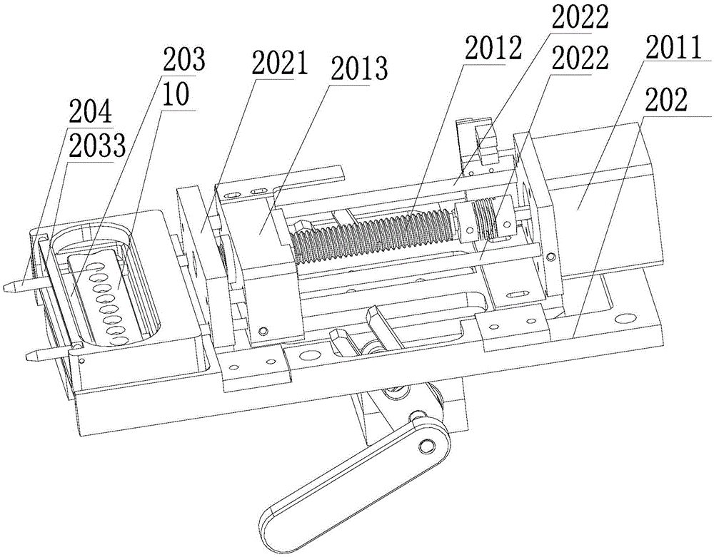
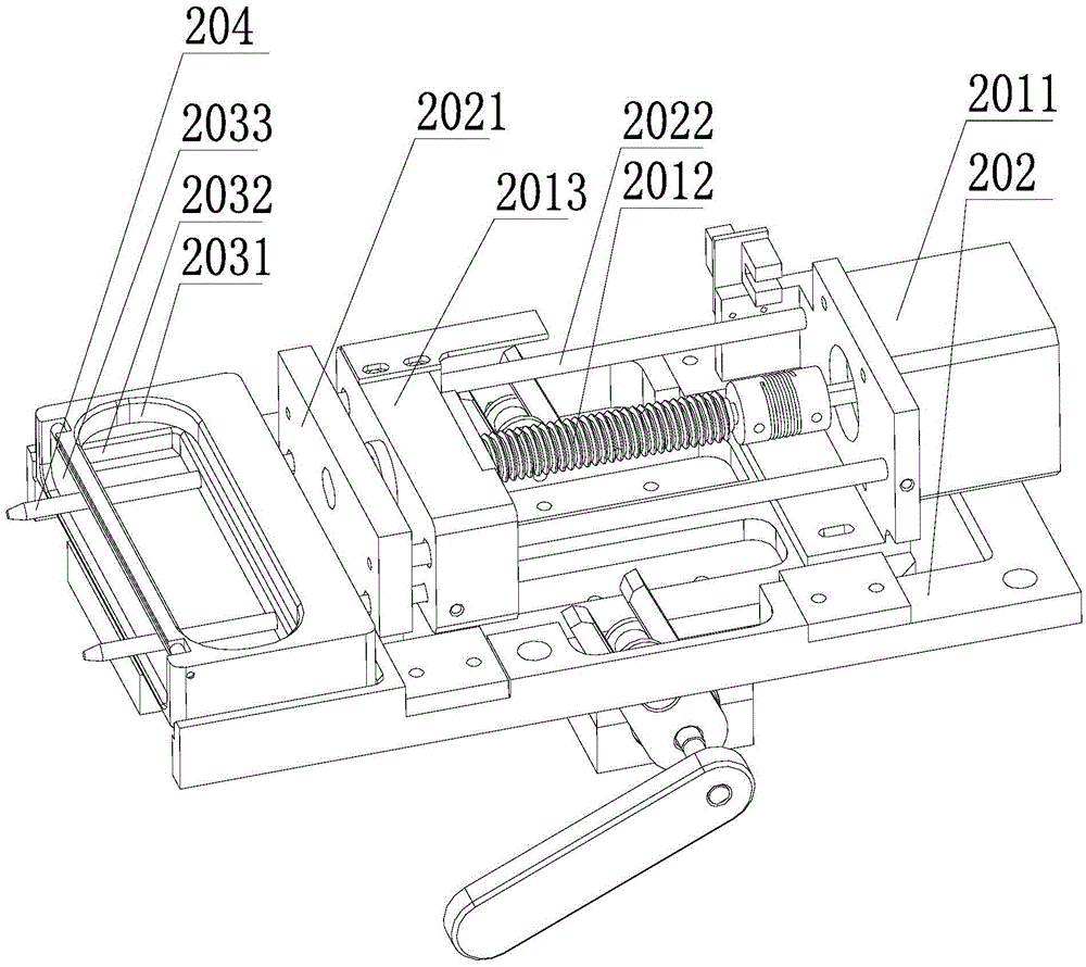
[0003] The purpose of the present invention is to provide a push device for reagent detection strips, which aims to solve the problem that the corresponding reagent dete

Method used


Image

  • Pushing device of reagent detection strips and full-automatic detection equipment with pushing device
  • Pushing device of reagent detection strips and full-automatic detection equipment with pushing device
  • Pushing device of reagent detection strips and full-automatic detection equipment with pushing device

Examples


Embodiment Construction

[0023] In order to make the object, technical solution and advantages of the present invention more clear, the present invention will be further described in detail below in conjunction with the accompanying drawings and embodiments. It should be understood that the specific embodiments described here are only used to explain the present invention, not to limit the present invention.

[0024] It should be noted that when an element is referred to as being “fixed on” or “disposed on” another element, it may be directly on the other element or there may be an intervening element at the same time. When an element is referred to as being "connected to" another element, it can be directly connected to the other element or intervening elements may also be present.

[0025] It should also be noted that the orientation terms such as left, right, up, and down in the embodiments of the present invention are only relative concepts or refer to the normal use state of the product, and should


PUM


Abstract

The invention belongs to the field of medical detection equipment and provides a pushing device of reagent detection strips and full-automatic detection equipment with the pushing device. The pushing device comprises a driving component, a plurality of pushing rods connected with the driving component, and a mounting groove matched with the pushing rods, a load bearing member containing and bearing multiple reagent detection strips is detachably connected on the mounting groove, and the pushing rods movably penetrate the mounting groove and are positioned below the load bearing member. By using a pushing component designed in that way, the problem that corresponding reagent detection strips need to be manually placed solely and the problem that detection results are influenced due to secondary pollution of the reagent detection strips in the prior art can be solved.

Description


Claims


Application Information

Patent Timeline
Owner 深圳市汇研科创生物科技有限公司
Why Eureka
Try Eureka