Push-pull force testing device for laminated packaging
A technology of push-pull force testing and stack packaging, which is applied in the direction of measuring devices, instruments, scientific instruments, etc., can solve the problems of low detection efficiency, chip replacement and long detection time, etc., to improve work efficiency, replacement efficiency and detection efficiency , Improve the effect of detection results
- Summary
- Abstract
- Description
- Claims
- Application Information
AI Technical Summary
Problems solved by technology
Method used
Image

Examples
Embodiment 1
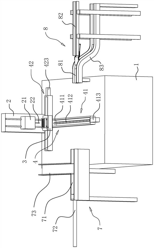
[0043] refer to figure 1 , the push-pull force testing device comprises a base 1, one end of the upper side of the base 1 is fixedly connected with a frame 2, and a push-pull force gauge 21 is slidably connected to the frame 2 along the vertical direction, and the inside of the frame 2 is arranged to drive the push-pull force gauge 21 to lift A lifting device, a test needle 22 is fixedly connected to the side of the push-pull force gauge 21 facing the base 1 .
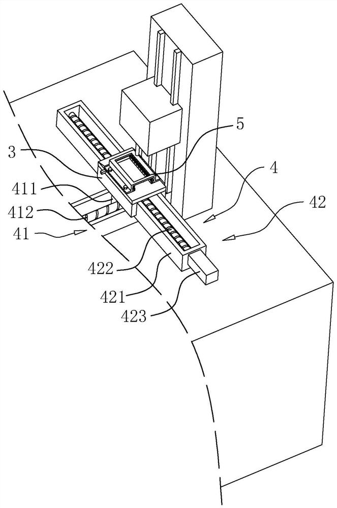
[0044] The other end on the upper side of the base 1 is provided with a workbench 3 , and a moving mechanism 4 connecting the two is provided between the base 1 and the workbench 3 . The moving mechanism 4 includes a first moving assembly 41 that moves along the Y-axis direction and a second moving assembly 42 that moves along the X-axis direction. Chips to be inspected are placed on the workbench 3 , wherein the chips are made by a package-on-package process.
[0045] refer to figure 1 and figure 2 , the first moving
Embodiment 2
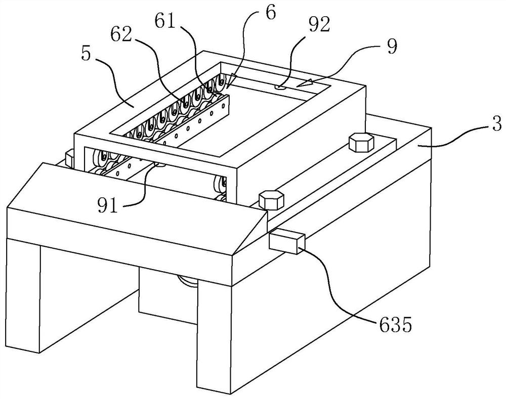
[0066] refer to Figure 9 and Figure 10 , the difference from Embodiment 1 is that a support assembly 31 for supporting and stabilizing the chip is provided between the workbench 3 and the pressing plate 5, the support assembly 31 includes a support block 311 parallel to the moving direction of the chip, one end of the support block 311 is connected to the working Table 3 is fixedly connected, and the other end is facing the pressing plate 5, and one end of the supporting block 311 facing the pressing plate 5 is connected with a number of supporting wheels 312 distributed along the length direction of the supporting block 311, and the circumference of the supporting wheel 312 is fixed with a number of evenly distributed suction cups 313 , the suction cup 313 on the side of the support wheel 312 close to the platen 5 presses against and adsorbs on the side wall of the chip.
[0067] When the chip moved in translation between the workbench 3 and the pressing plate 5, the suction
PUM
 Abstract
Description
Claims
Application Information
 - R&D Engineer
- R&D Manager
- IP Professional
- Industry Leading Data Capabilities
- Powerful AI technology
- Patent DNA Extraction
Browse by: Latest US Patents, China's latest patents, Technical Efficacy Thesaurus, Application Domain, Technology Topic.
© 2024 PatSnap. All rights reserved.Legal|Privacy policy|Modern Slavery Act Transparency Statement|Sitemap