Self-circulating type garbage disposal equipment

A garbage disposal equipment and self-circulating technology, applied in lighting and heating equipment, combustion methods, combustion types, etc., can solve problems such as waste of resources, and achieve the effect of reducing total cost and operating cost

Inactive Publication Date: 2016-06-15
SINOBIOWAY BIOENVIRONMENT CO LTD
View PDF6 Cites 2 Cited by
  • Summary
  • Abstract
  • Description
  • Claims
  • Application Information

AI Technical Summary

Problems solved by technology

In the existing garbage disposal technologies, most of them treat garbage as the object to be proces

Method used


Image

  • Self-circulating type garbage disposal equipment
  • Self-circulating type garbage disposal equipment
  • Self-circulating type garbage disposal equipment

Examples


Embodiment Construction

[0034] Below, the technical solution of the present invention will be described in detail through specific examples.

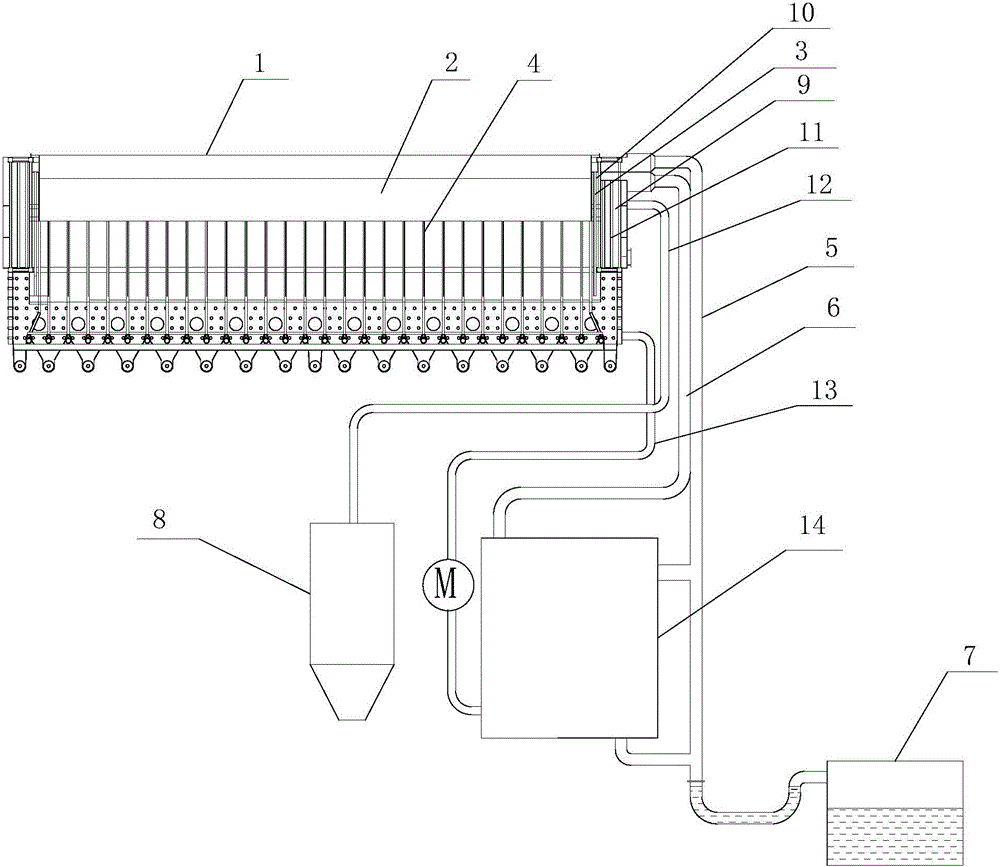
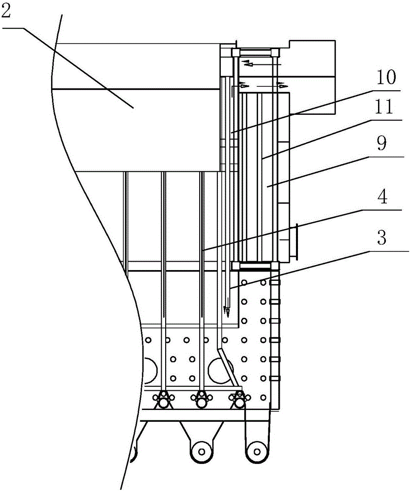
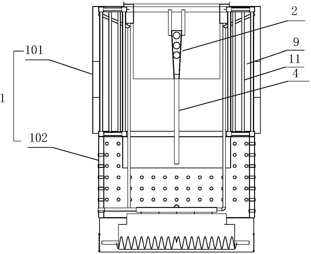
[0035] Such as Figure 1-3 as shown, figure 1 It is a schematic structural diagram of a self-circulating garbage disposal device proposed by the present invention; figure 2 It is a partially enlarged view of a self-circulating garbage disposal device proposed by the present invention; image 3 It is a side view of a self-circulating garbage disposal device proposed by the present invention.

[0036] refer to Figure 1-3 , a self-circulating garbage disposal device proposed by the embodiment of the present invention, comprising: a gasifier 1, an air intake device 2, an internal circulation pipe 3, a first air guide pipe 4, a second air guide pipe 5, and a third air guide pipe 6 , a first induced draft fan (not shown in the figure), a second induced draft fan (not shown in the figure), a water cooling device 14, a water tank 7 and an exhaust gas purification d


PUM


Abstract

The invention discloses self-circulating type garbage disposal equipment which comprises a gasification furnace, a gas inlet device, an inner circulating pipe, first gas guide pipes, a second gas guide pipe, a third gas guide pipe, a first induced draft fan, a second induced draft fan, a water cooling device, a water tank and a tail gas purification device. The gasification furnace comprises an upper furnace body and a lower furnace body. The furnace wall of the upper furnace body is provided with a smoke discharge cavity, the smoke discharge cavity is provided with a smoke discharge opening and a smoke inlet channel, and the smoke discharge opening is connected with the tail gas purification device through a pipeline and the second induced draft fan. A return smoke cavity is formed in the upper furnace body and provided with a return smoke inlet and a return smoke outlet. The gas inlet device communicates with the return smoke cavity. One end of each first gas guide pipe is connected with the gas inlet device, and the other end of each first gas guide pipe is located in the lower furnace body. One end of the inner circulating pipe is connected with the return smoke inlet, and the other end of the inner circulating pipe extends into the lower furnace body. The two ends of the second gas guide pipe are connected with the return smoke outlet and the water cooling device. One end of the third gas guide pipe is connected with the return smoke inlet, and the other end of the third gas guide pipe is connected with the water cooling device through the first induced draft fan. The water tank is connected with the water cooling device.

Description


Claims


Application Information

Patent Timeline
Owner SINOBIOWAY BIOENVIRONMENT CO LTD
Why Eureka
Try Eureka