A sealing zipper

A technology for sealing zippers and zipper teeth, applied in the field of zippers, can solve the problems of easy wear and tear, inconvenient production, abruptness, etc., and achieve the effects of not easy to crack or leak, labor-saving during the pulling and closing process, and high commercial utility.

Inactive Publication Date: 2016-06-22
黄小松
View PDF6 Cites 0 Cited by
  • Summary
  • Abstract
  • Description
  • Claims
  • Application Information

AI Technical Summary

Benefits of technology

This patented technology simplifies the design of an enclosed zippers used for these purposes while also reducing costs compared to existing designs without requiring any extra treatments at both ends. It achieves this through creation of two magnet strips parallel to each other within a single piece of material called a base film made from plastic foam (foamed polyurethane). These stripes are then covered over onto one another when pulled together like cords attached around rings. When closed, there're only needed to apply pressure twice before opening them again. By doing things properly, the zapper can achieve effective seals even if they get bent due to environmental factors such as temperature changes or moisture.

Problems solved by technology

This patented technical problem addressed by this patents relates to improving the ease and efficiency when attaching zigzagged belts together for better functionality during dive houseings without causing any difficulties such as excessively tightened knots due to insufficient lubrication caused by contact between different materials like fabric material.

Method used


Image

  • A sealing zipper
  • A sealing zipper
  • A sealing zipper

Examples


Embodiment 1

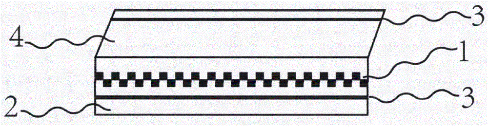
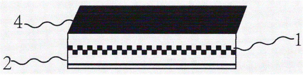
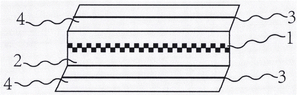
[0033] An airtight zipper such as figure 1 As shown, the airtight zipper includes a base cloth 3, a first zipper element 1, a second zipper element 2 and a zipper puller, and a first mask 6 is arranged on the base cloth 3 on the side of the first zipper element 1. The masking sheet 6 is seamlessly joined with the base fabric 3 , and the first magnetic strip 4 is provided on the first masking sheet 6 along the opening and closing direction of the first zipper element 1 and the second zipper element 2 .

[0034] A second magnetic strip 5 is provided at a position corresponding to the first magnetic strip 4 on one side of the second zipper element 2, so that when the first magnetic strip 4 and the second magnetic strip 5 are fastened together, the first mask 6 covers the The closed first zipper element 1 and the second zipper element 2 make the accommodating chamber using the sealed zipper form a sealed space.

[0035] The second magnetic strip 5 can be arranged on the base cloth


PUM


Abstract

The invention provides a sealing zipper which is concise in structure. No special treatment is needed between zipper teeth; the pulling process is labor-saving; a covering piece covers the engaged zipper teeth under the attraction of magnetic strips so that an accommodating cavity using the sealing zipper forms a sealing space. The binding force of the magnetic joint force and the stress on the zipper are not on the same plane, so that under general using conditions, the zipper is not liable to cracking or leak caused by external force. The sealing zipper is suitable for domestic sealing in daily life and such products like sealing disinfecting bags, and has higher commercial practical value.

Description


Claims


Application Information

Patent Timeline
Owner 黄小松
Why Eureka
Try Eureka