Communication antenna, antenna system and communication device

A technology for communication antennas and antenna systems, which is applied to the connection of antennas, antenna grounding switch structures, and the combination of antenna units with different polarization directions. Reduced volume, small volume, low profile effect

Pending Publication Date: 2016-10-05
KUANG CHI CUTTING EDGE TECH LTD
View PDF7 Cites 3 Cited by
  • Summary
  • Abstract
  • Description
  • Claims
  • Application Information

AI Technical Summary

Benefits of technology

This patented technology improves upon previous designs for communications radios but it still requires bulky components like lenses and reflectors. It achieves this through creation of an asymmetric structure called a double layer radiater, resulting in smaller dimensions while maintaining high performance at specific frequencies. Additionally, there're certain benefits associated with combining these techniques into a single device, reducing its overall thickness and weight. Overall, this new approach simplifies manufacturing processes and makes possible applications involving both radio frequency identification systems and wireless local area network technologies.

Problems solved by technology

The technical problem addressed in this patents relates to improving the efficiency at which two types of antenna can operate simultaneously: one type operates on both low frequencies and another type operating on all three sides - either alone or together. This requires that each antenna element produces its own unique waveform without interference from other elements. Additionally, there may also exist situations where even if only certain parts of the antennage require greater amplification than others.

Method used


Image

  • Communication antenna, antenna system and communication device
  • Communication antenna, antenna system and communication device
  • Communication antenna, antenna system and communication device

Examples


Embodiment Construction

[0047] The present invention will be further described below in conjunction with specific embodiment and accompanying drawing, set forth more details in the following description so as to fully understand the present invention, but the present invention can obviously be implemented in many other ways different from this description, Those skilled in the art can make similar promotions and deductions based on actual application situations without violating the connotation of the present invention, so the content of this specific embodiment should not limit the protection scope of the present invention.

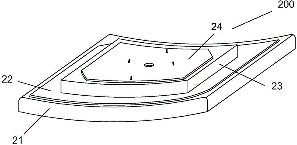
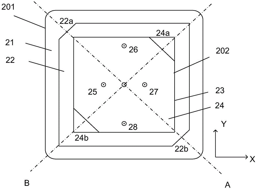
[0048]figure 1 A schematic three-dimensional structural diagram showing a schematic diagram of a microstrip communication antenna according to an embodiment of the present invention. figure 2 A plan view showing an exemplary communication antenna structure according to an embodiment of the present invention. refer to figure 1 and figure 2 As shown, the communication antenna 20


PUM


Abstract

The present invention relates to a communication antenna, an antenna system including the communication antenna, and a communication device including the antenna. The communication antenna comprises a first radiator having a first substrate and a first radiation fin arranged on the first substrate, wherein the first radiation fin has a first feed portion and a third feed portion; and a second radiator having a second substrate and a second radiation fin arranged on the second substrate, wherein the first radiation fin has a second feed portion and a fourth feed portion, the radiating surfaces of the first radiation fin and the second radiation fin are recessed surfaces, the first radiation fin and the second radiation fin respectively have corner cuts, and the first radiator and the second radiator are disposed in a lamination mode.

Description


Claims


Application Information

Patent Timeline
Owner KUANG CHI CUTTING EDGE TECH LTD
Why Eureka
Try Eureka