Automatic material discharging control device

A technology of automatic control device and automatic control system, which is applied in the directions of transportation, packaging, loading/unloading, etc., can solve the problems that the discharge volume cannot be automatically controlled, and cannot be automatically discharged, and achieves ingenious structural design, reasonable structural design, and good quality. The effect of the application foreground

Inactive Publication Date: 2016-11-23
宾际云
View PDF0 Cites 0 Cited by
  • Summary
  • Abstract
  • Description
  • Claims
  • Application Information

AI Technical Summary

Problems solved by technology

[0004] The purpose of the present invention is to solve the technical problems in the above-mentioned prior art that the material cannot be automatically discharged and the output volume cannot be automatically controlled, and to provide an automatic discharge control device that can automatically discharge materials and control the discharge volume.

Method used


Image

  • Automatic material discharging control device

Examples


Example Embodiment

[0013] Example 1

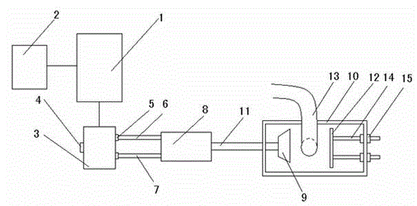
[0014] An automatic control device for discharging of this embodiment, refer to the attachment figure 1 , Including the automatic control system 1 installed on the rack, the automatic control system 1 is connected to the electronic scale 2, and the automatic control system 1 is also connected to the reversing valve 3. The reversing valve 3 is provided with an air inlet 4 and two There are two air outlets 5, and the two air outlets 5 are respectively connected to the air duct I6 and the air duct II7. The air duct I6 and the air duct II7 are both connected to the cylinder 8, and the output shaft 11 of the cylinder 8 is connected with a push plate 9. A square frame 10 is also installed on the frame. One side wall of the square frame 10 is provided with a through hole for passing the output shaft 11, and the opposite side wall of the square frame 10 is equipped with a stopper for use with the push plate 9. The plate 12 and the discharge hose 13 are arranged between t


PUM


Abstract

The invention relates to a material discharging device, in particular to an automatic material discharging control device. The automatic material discharging control device comprises an automatic control system installed on a rack. The automatic control system is in control connection with an electronic scale. The automatic control system is also in control connection with a reversing valve. The reversing valve is provided with an air inlet and two air outlets. The two air outlets are connected with an air guide pipe I and an air guide pipe II correspondingly. Both the air guide pipe I and the air guide pipe II communicate with an air cylinder. An output shaft of the air cylinder is connected with a push plate. The rack is further provided with a square frame. A through hole allowing the output shaft to pass through is formed in the side wall of one face of the square frame, and a baffle matched with the push plate for use is installed on the side wall of the opposite face of the square frame. A discharging hose is arranged between the push plate and the baffle. The automatic material discharging control device can achieve automatic material discharging; and moreover, the quantity of discharged materials can be controlled, and using is quite convenient.

Description


Claims


Application Information

Patent Timeline
Owner 宾际云
Why Eureka
Try Eureka