Constant-speed harmonic speed reducer

A technology of harmonic reducer and harmonic generator, applied in the direction of belt/chain/gear, mechanical equipment, transmission device, etc., which can solve unreasonable design, unstable speed of harmonic generator, uncontrollable speed of servo motor, etc. problem, to achieve the effect of stable speed and controllable state

Inactive Publication Date: 2016-11-23
广东天太机器人有限公司
View PDF0 Cites 0 Cited by
  • Summary
  • Abstract
  • Description
  • Claims
  • Application Information

AI Technical Summary

Benefits of technology

This patented technology improves upon existing generators by adding an engine end cap or other feature for connection between the damper's rotor drive mechanism (the servo) and its output shaffer. By fixing this component directly onto the machine itself instead of relying solely on it being driven by another part like the serrodyne reducers described earlier, there will have more stability during operation due to the use of a special structure called a connector used to connect them together. Additionally, when the servomotors move backward from their normal operating mode they also experience less resistance than before moving forward again. Overall, these technical improvements improve efficiency and performance of the machines involved.

Problems solved by technology

This patented technical problem addressed in this patents relating to harmonically driven machines involves controlling the output torque based upon input frequency or amplitude variations caused by fluctuations such as temperature variation during operation. Current methods for achieving these goals have limitations due to instability issues associated with electrical systems used for control purposes.

Method used


Image

  • Constant-speed harmonic speed reducer
  • Constant-speed harmonic speed reducer
  • Constant-speed harmonic speed reducer

Examples


Embodiment Construction

[0015] In order to have a further understanding and understanding of the structural features of the present invention and the achieved effects, the preferred embodiments and accompanying drawings will be used for a detailed description, as follows:

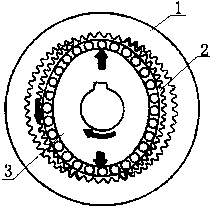
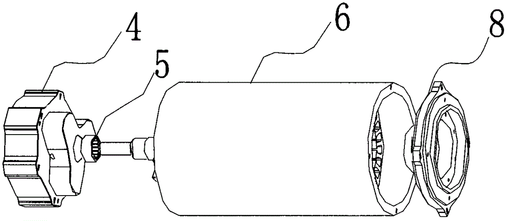
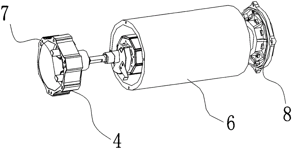
[0016] Such as Figure 1 to Figure 3 As shown, a steady-speed harmonic reducer includes a rigid wheel 1, the rigid wheel 1 is connected with a flexible wheel 2, and the flexible wheel 2 is connected with a harmonic generator 3 connected to a servo motor for rotation, and the harmonic generation One side of the generator 3 is provided with a generator end cover 4, and the generator end cover 4 is provided with a connection hole, and the connection hole is connected with the output shaft of the servo motor 6 through a needle bearing 5; the tail of the servo motor 6 is provided with a Hall Control system 8, the Hall control system 8 includes a drive board with a signal acquisition module, a logic processing module and a motor drive modu


PUM


Abstract

The invention relates to a constant-speed harmonic speed reducer. The constant-speed harmonic speed reducer comprises a rigid gear, wherein a flexible gear is connected in the rigid gear in a transmission manner, a harmonic generator connected with a servo motor is connected in the flexible gear in a rotating manner, a generator end cover is arranged at one side of the harmonic generator, a connecting hole is formed in the generator end cover, the connecting hole is connected with an output shaft of the servo motor through a needle roller bearing, and the rotating speed of the harmonic generator connected with the generator end cover is stabilized; and a Hall control system is arranged at the tail of the servo motor, a starting Hall position, a high-speed Hall position, a low-speed Hall position and a closing Hall position are arranged on a Hall stroke plate, and the rotating state of the servo motor is controlled through the different Hall positions so as to achieve a purpose of enabling the state of the servo motor to be controllable.

Description


Claims


Application Information

Patent Timeline
Owner 广东天太机器人有限公司
Why Eureka
Try Eureka