Monitoring method of internal stress of spacecraft composite material structure in aging process

A composite material and aging process technology, which is applied in the direction of measurement, instrumentation, and force measurement by measuring the change in optical properties of the material when it is stressed, can solve the problem of low resolution and the inability to achieve high resolution of the internal stress of the composite material structure Measurement and other issues, to achieve high spatial resolution, improve dimensional stability, and good repeatability

Inactive Publication Date: 2017-04-26
SHANGHAI INST OF SATELLITE EQUIP
View PDF5 Cites 12 Cited by
  • Summary
  • Abstract
  • Description
  • Claims
  • Application Information

AI Technical Summary

Benefits of technology

The present invent describes an improved way to age fiber reinforced plastic (FRP) materials used inside spaceships without affecting their overall dimensions or shape during use. This technique uses light waves that reflect from certain parts of these FRMs instead of relying solely upon them themselves. By measuring this reflected signals over time we can monitor how well they are doing under different conditions such as temperature changes or pressure variations. These techniques have several benefits including higher sensitivity, better precision measurements, and more reliable results compared to previous methods like ultrasonics.

Problems solved by technology

This patented technical solution described by this patents relates to improving the quality control (QC) performance of space vehicles' structural components due to their potential negative effects caused by external forces like vibrational waves generated when they hit them overheated at certain temperatures. To address these concerns, an improved method called laser resonance technique has been developed. Laser resonant techniques use special glass compositions made up of fine wires embedded within the composite structure itself to detect any slight variations in temperature without affecting other important properties. These techniques provide precise measurements while also allowing continuous monitoring throughout the entirety of the structure being aged.

Method used


Image

  • Monitoring method of internal stress of spacecraft composite material structure in aging process
  • Monitoring method of internal stress of spacecraft composite material structure in aging process
  • Monitoring method of internal stress of spacecraft composite material structure in aging process

Examples


Embodiment Construction

[0023] The present invention will be described in detail below in conjunction with specific embodiments. The following examples will help those skilled in the art to further understand the present invention, but do not limit the present invention in any form. It should be noted that those skilled in the art can make several modifications and improvements without departing from the concept of the present invention. These all belong to the protection scope of the present invention.

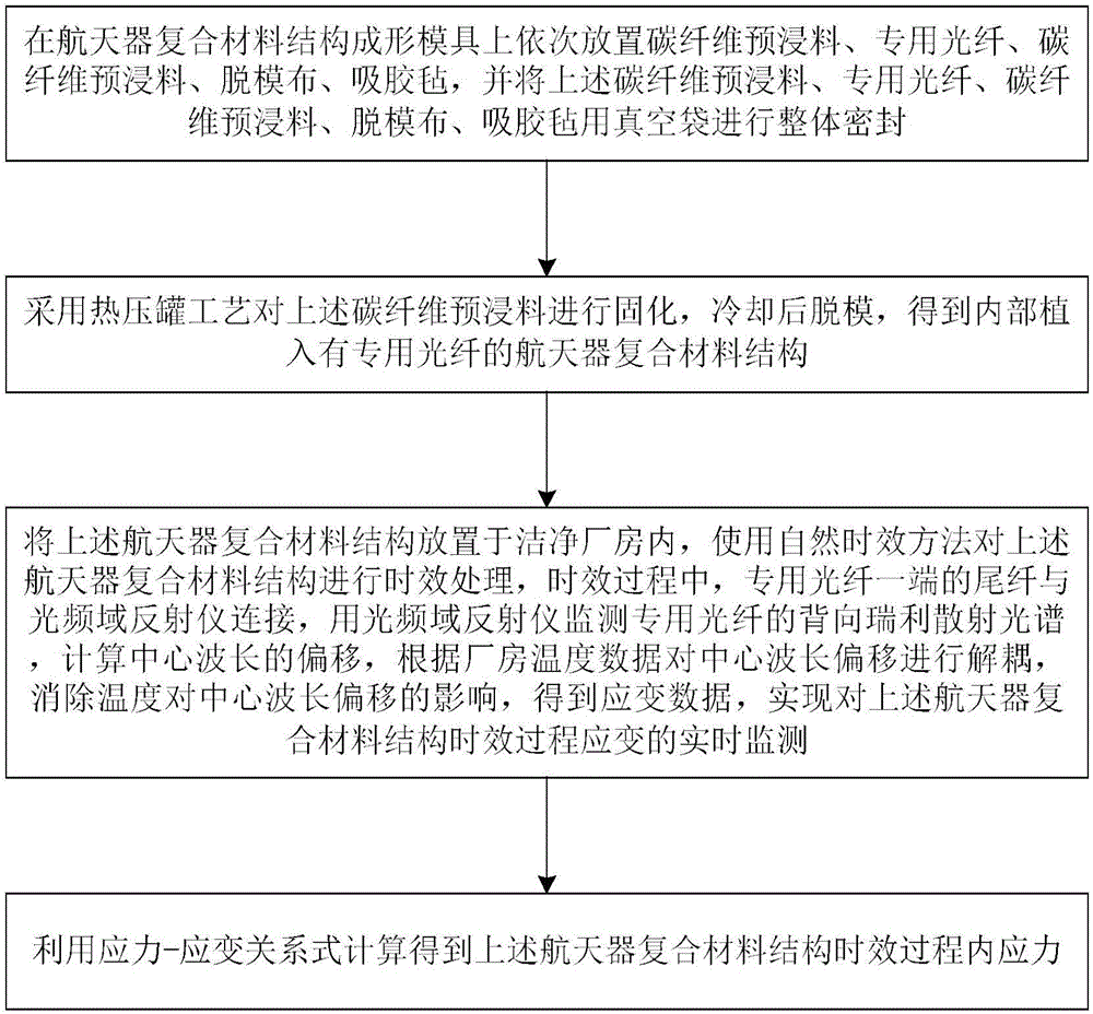
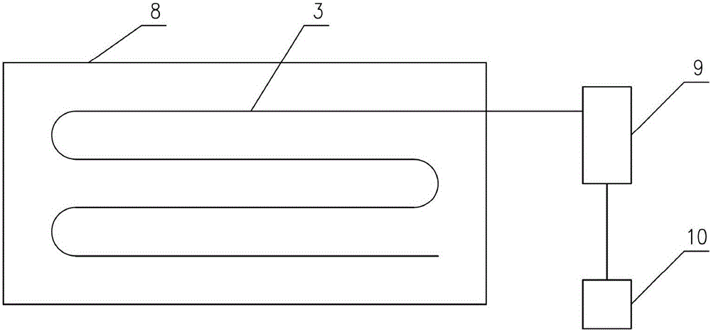
[0024] Such as figure 1 As shown, the method for monitoring the internal stress of the spacecraft composite structure aging process of the present invention comprises the following steps:

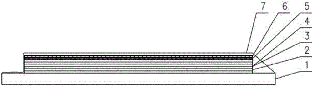
[0025] Step one, such as figure 2 As shown, carbon fiber prepreg 2, special optical fiber 3, carbon fiber prepreg 2, release cloth 5, and adhesive felt 6 are sequentially placed on the spacecraft composite structure forming mold 1, and the above carbon fiber prepreg 2, The special optical fiber 3, the carbon fi


PUM

PropertyMeasurementUnit
Diameteraaaaaaaaaa

Abstract

The invention provides a monitoring method of the internal stress of a spacecraft composite material structure in an aging process. The method includes following steps: step1, placing carbon fiber prepreg, a special optical fiber, carbon fiber prepreg, demolding cloth, and adhesive-absorbing felt on a molding mold of the spacecraft composite material structure in sequence, and performing integral sealing by employing a vacuum bag; step 2, performing curing by employing an autoclave process, performing demolding after cooling, and obtaining the spacecraft composite material structure implanted with the special optical fiber at the inner part; and step 3, placing the spacecraft composite material structure in a clean factory building, and performing aging treatment on the spacecraft composite material structure by employing a natural aging method. According to the method, based on a back Rayleigh scattering principle, the special optical fiber is implanted in the spacecraft composite material structure, the monitoring of the internal stress in the aging process is realized by employing an optical frequency domain reflection technology, the spatial resolution is high, the measuring precision is high, the repeatability is good, and basis is laid for improvement of the aging method of the spacecraft composite material structure and the improvement of the dimension stability.

Description


Claims


Application Information

Patent Timeline
Owner SHANGHAI INST OF SATELLITE EQUIP
Why Eureka
Try Eureka