Electric field change measurement device and method
A measurement device and electric field change technology, applied in the direction of measurement device, electrostatic field measurement, measurement of electrical variables, etc., can solve the problem of affecting the detection ability of long-distance weak electric field change signals, reducing the dynamic range of output signals, and not having a perfect solution, etc. problem, to achieve the effect of improving dynamic range, eliminating resonance and reducing cost
- Summary
- Abstract
- Description
- Claims
- Application Information
AI Technical Summary
Benefits of technology
Problems solved by technology
Method used
Image

Examples
Embodiment 1
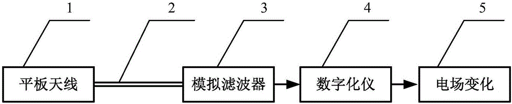
[0068] A preferred embodiment of the present invention employs figure 1 shown in the block diagram of the structure. In the thunderstorm environment, the signal induced by the panel antenna 1 is connected to the analog filter 3 through the coaxial cable 2 . In a preferred embodiment, the planar antenna equivalent capacitance C a It is 10pF; the transmission line length is 10m, the characteristic impedance is 50Ω, and the wave speed is 2×10 8 m / s coaxial cable; the sampling rate of the digitizer is 30MS / s, the internal anti-aliasing filter is 0-15MHz low-pass filter, the equivalent input resistance of the input port is 1MΩ, and the input capacitance is 5pF. The input impedance of the analog filter 3 is designed to be 50 ohms, matching the coaxial cable.
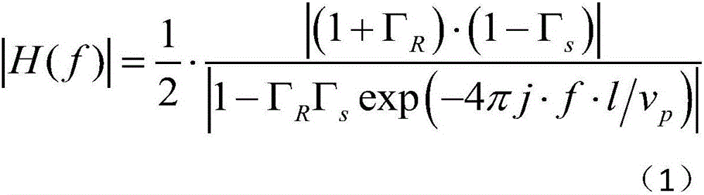
[0069] According to formula (1), the first resonance frequency point fc of the system amplitude-frequency response is obtained 1 =9.879MHz, amplitude |H((fc 1 )|=11.27, the amplitude-frequency response of the system |H(f
Embodiment 2
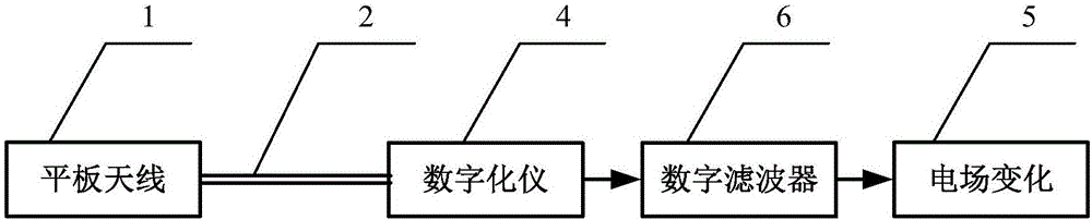
[0072] A preferred embodiment of the present invention employs figure 2 shown in the block diagram of the structure. In the thunderstorm environment, the signal induced by the flat panel antenna 1 is directly connected to the digitizer 4 through the coaxial cable 2 . After sampling by the digitizer 4, a digital filter is designed by using the digital signal processing technology of software or hardware, and the digital signal is filtered to obtain the final electric field change digital signal. In a preferred embodiment, the planar antenna equivalent capacitance C a It is 10pF; the transmission line length is 10m, the characteristic impedance is 50Ω, and the wave speed is 2×10 8 m / s coaxial cable; the sampling rate of the digitizer is 30MS / s, the anti-aliasing filter is a 0-15MHz low-pass filter, the equivalent input resistance of the input port is 1MΩ, and the input capacitance is 5pF.
[0073] The design principle of the digital filter 6 is similar to that of the analog
PUM
| Property | Measurement | Unit |
|---|---|---|
| Equivalent capacitance | aaaaa | aaaaa |
Abstract
Description
Claims
Application Information
 - R&D Engineer
- R&D Manager
- IP Professional
- Industry Leading Data Capabilities
- Powerful AI technology
- Patent DNA Extraction
Browse by: Latest US Patents, China's latest patents, Technical Efficacy Thesaurus, Application Domain, Technology Topic.
© 2024 PatSnap. All rights reserved.Legal|Privacy policy|Modern Slavery Act Transparency Statement|Sitemap