Electromagnetic engine

A technology of electromagnetic motor and electromagnet, applied in the field of power machinery, can solve the problems of low efficiency of power source, complex structure of electromagnetic motor, polarization of electromagnet coil, etc., and achieve the effect of high-efficiency power source, simple structure and long-lasting power source

Pending Publication Date: 2017-05-31
王明哲
View PDF1 Cites 3 Cited by
  • Summary
  • Abstract
  • Description
  • Claims
  • Application Information

AI Technical Summary

Benefits of technology

This patented technology allows for better control over how electricity flows through magnets used with electronic devices such as speakers or microphones. It simplifies its construction while also allowing for adjusting their properties based on factors like temperature changes without affecting other components that are sensitive to these variables.

Problems solved by technology

Invention describes an improved way for generating electrically generated power from moving parts without consuming too much fossile materials during their lifetimes.

Method used


Image

  • Electromagnetic engine
  • Electromagnetic engine
  • Electromagnetic engine

Examples


Embodiment 1

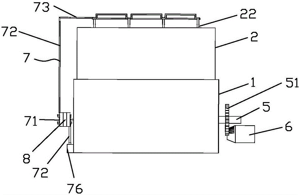
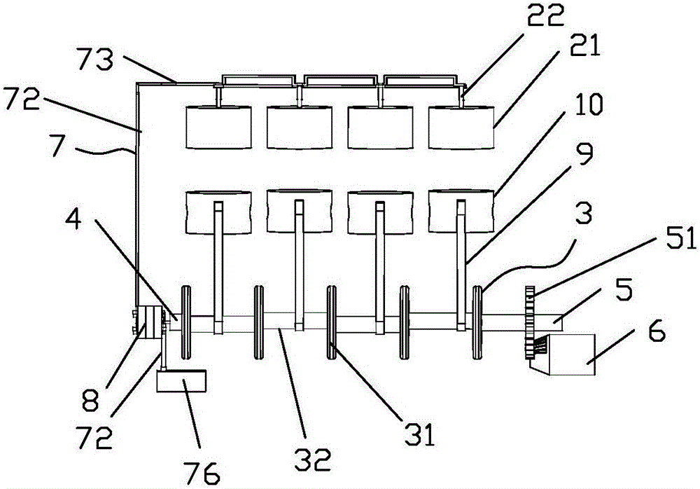
[0031] The present embodiment 1 provides an electromagnetic motor, with reference to figure 1 and figure 2 As shown, it includes a first housing 1 with an opening on the upper end surface and a second housing 2 arranged on the first housing 1 and communicating with the first housing 1. During the specific implementation of the present invention, the second housing 2 The lower end surface of the second housing is provided with a lower opening that communicates with the opening of the first housing; wherein, a crank wheel assembly 3 is horizontally arranged in the first housing 1, and one end of the crank wheel assembly 3 is connected with a cable that passes through the first housing. 1 small crankshaft connecting rod 4 on one side wall, the other end of the crank wheel assembly 3 is connected with the first crankshaft connecting rod 5 protruding from the other side wall symmetrical to the side wall of the first housing 1, protruding out of the first housing The first crankshaft

Embodiment 2

[0044] An electromagnetic motor, the difference between this electromagnetic motor and embodiment 1 is that the electromagnetic motor also includes an electrode converter frame 11, refer to Figure 11 As shown, the electrode converter frame 11 includes a bushing 12 that is sleeved on the electrical connection base block 81 away from the crankshaft small connecting rod 4. A plurality of shaft rods 13, the shaft rods 13 penetrate into the first housing 1, and the electrode converter frame is provided to stabilize the electrode converter.

[0045] refer to Figure 10 As shown, the two electrode columns 22 on the same electromagnet 21 are sleeved with an insulating ring 23, which has a good insulation effect and prevents leakage.


PUM


Abstract

The invention provides an electromagnetic engine. The electromagnetic engine comprises a first shell and a second shell which is arranged on the first shell and communicated with the first shell, wherein a curved wheel assembly is horizontally arranged in the first shell; one end of the curved wheel assembly is connected with a small curved shaft connecting rod which penetrates through a side wall of the first shell, and the other end of the curved wheel assembly is connected with a first curved shaft connecting rod which extends out of another side wall symmetric to the side wall of the first shell; the part, extending out of the first shell, of the first curved shaft connecting rod is sleeved with a gear; the gear is meshed with a starting motor; the small curved shaft connecting rod which penetrates through the side wall of the first shell is connected with an electrode converter; connecting rods are arranged on the curved wheel assembly; the end portion of each connecting rod is connected with a movable permanent magnet; electromagnets corresponding to the movable permanent magnets in position are arranged on the upper end face of the second shell in a penetrating manner. The electromagnetic engine is simple in structure, solves the problem in the prior art that an electromagnetic coil is easy to polarize, and can provide a high-efficient durable power source for the electromagnetic engine.

Description


Claims


Application Information

Patent Timeline
Owner 王明哲
Why Eureka
Try Eureka