Focusing apparatus and camera module testing apparatus

A focus ring and fine adjustment technology, applied in the field of photography, can solve the problems of increased focus time, over-adjustment or under-adjustment, low adjustment accuracy, etc., and achieve the effects of improved accuracy, reduced thickness, and convenient operation

Active Publication Date: 2017-06-06
GOERTEK OPTICAL TECH CO LTD
View PDF4 Cites 3 Cited by
  • Summary
  • Abstract
  • Description
  • Claims
  • Application Information

AI Technical Summary

Benefits of technology

The inventive feature described in this patented design allows for easy adjustments when focused on specific areas or parts within an image without having to move it around all over again. This makes it easier than previous designs where multiple components were needed. Additionally, there are fewer constraints with these devices due to their compact size compared to traditional methods like lenses. Overall, they make imaging systems more efficient while reducing its overall dimensions.

Problems solved by technology

This patented technical solution describes an issue with current manual rotation of focused rings in cameras modules due to their poor alignment precision when changing lens settings during testing. Additionally, there are limitations on how well they can achieve automatic focus by moving them closer together from one device to another without requiring excessive effort.

Method used


Image

  • Focusing apparatus and camera module testing apparatus
  • Focusing apparatus and camera module testing apparatus
  • Focusing apparatus and camera module testing apparatus

Examples


Embodiment Construction

[0031] Various exemplary embodiments of the present invention will now be described in detail with reference to the accompanying drawings. It should be noted that the relative arrangements of components and steps, numerical expressions and numerical values ​​set forth in these embodiments do not limit the scope of the present invention unless specifically stated otherwise.

[0032] The following description of at least one exemplary embodiment is merely illustrative in nature and in no way taken as limiting the invention, its application or uses.

[0033] Techniques, methods and devices known to those of ordinary skill in the relevant art may not be discussed in detail, but where appropriate, such techniques, methods and devices should be considered part of the description.

[0034] In all examples shown and discussed herein, any specific values ​​should be construed as exemplary only, and not as limitations. Therefore, other instances of the exemplary embodiment may have differ


PUM


Abstract

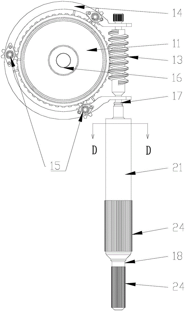
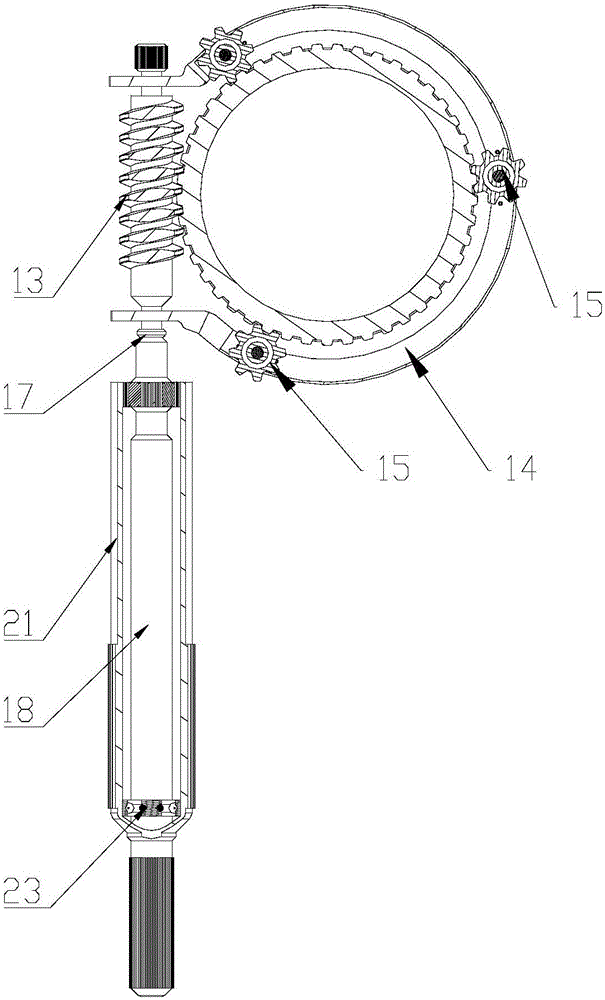
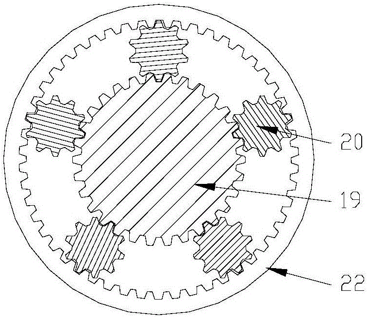
The invention discloses a focusing apparatus and a camera module testing apparatus. The focusing apparatus comprises a focusing ring, a worm, a support and a driving part. The focusing ring and the worm are both in rotary connection with the support. The outer peripheral side of the focusing ring is provided with teeth that surround the outer peripheral side and match the worm. The focusing ring and the worm form a worm and gear mechanism. The driving part is configured to drive the worm to rotate. The focusing apparatus has the characteristics of realizing convenient focusing and being high in focusing precision.

Description


Claims


Application Information

Patent Timeline
Owner GOERTEK OPTICAL TECH CO LTD
Why Eureka
Try Eureka