A retaining and clamping device for high-frequency circumferential small tenon blade vibration fatigue test and its use method

A vibration fatigue and clamping device technology, applied in vibration testing, measuring devices, testing of machine/structural components, etc., can solve the problems affecting the normal operation of vibration fatigue testing, difficulty in processing, damage to retention and clamping devices, etc. The effect of stable fixing, reducing processing difficulty and improving efficiency

Active Publication Date: 2019-03-01
CHENGDU ENGINE GROUP
View PDF8 Cites 1 Cited by
  • Summary
  • Abstract
  • Description
  • Claims
  • Application Information

AI Technical Summary

Problems solved by technology

Due to the small mortise and groove, it is not only difficult to process, but also the retention and clamping device is easily damaged due

Method used


Image

  • A retaining and clamping device for high-frequency circumferential small tenon blade vibration fatigue test and its use method
  • A retaining and clamping device for high-frequency circumferential small tenon blade vibration fatigue test and its use method
  • A retaining and clamping device for high-frequency circumferential small tenon blade vibration fatigue test and its use method

Examples


Example Embodiment

[0028] Example 1

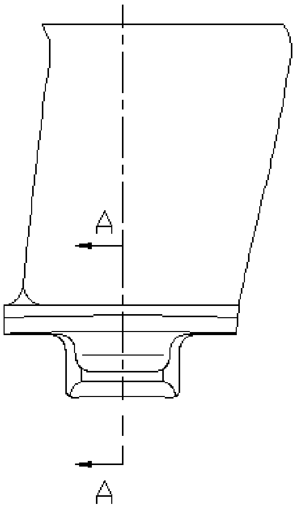
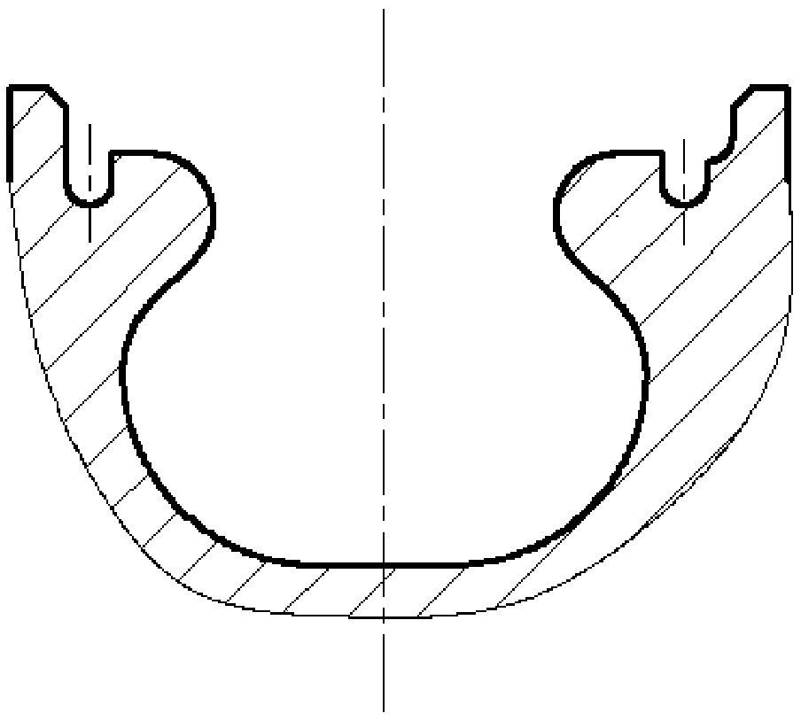
[0029] In this embodiment, the structure of the retaining and clamping device for the vibration fatigue test of the high-frequency circumferential small tenon blade is as follows: Figure 4 , Figure 5 , Image 6 As shown, it is mainly composed of upper tightening bolt 1, force transmission retention strip 2, clamp 3, bracket 4, adapter plate 5, rear tightening bolt 6, rear tightening back cap 7 and auxiliary blade 8.

[0030] The tested blade 9 such as figure 1 , figure 2 As shown, the auxiliary blade 8 has the same shape and size as the tested blade 9; the adapter plate 5 is as Figure 4 , Figure 5 As shown, it is a circular plate body;

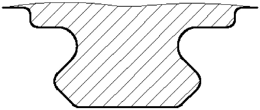
[0031] force transmission retaining strip 2 such as Figure 8 As shown, it includes a guide bar 2-1 and a top bar 2-2 that is an integrated structure with the guide bar, and one end of the force transmission and retention bar 2 is provided with a limit block 2-3, and the guide bar 2-1 and the top bar 2-2 are quadra

Example Embodiment

[0034] Example 2

[0035] This embodiment uses the retaining clamping device described in embodiment 1 to figure 1 , figure 2 The blade is clamped and fixed on an electromagnetic vibrating table for a vibration fatigue test. The operation is as follows:

[0036] ① Fix the adapter plate 5 on the surface of the electromagnetic vibration table with bolts, and then fix the fixture 3 on the adapter plate with bolts, and the center line of the fixture 3 coincides with the center line of the adapter plate 5;

[0037]②Fix the bracket 4 on the adapter plate 5 with bolts. The fixing position of the bracket 4 should be such that the fixture 3 is located under the top plate of the bracket 4 and the second screw hole set on the top plate, the tenon of the auxiliary blade and the tenon of the blade to be tested are installed in the fixture. The installation position on the clip body 3-2 corresponds;

[0038] ③Insert the force transmission retaining strip 2 into the groove cavity 3-2-1 prov


PUM


Abstract

The invention relates to a high-frequency circumferential small-tenon blade vibration fatigue test retaining and clamping device. The high-frequency circumferential small-tenon blade vibration fatigue test retaining and clamping device comprises an upper puller bolt, a force transmission retaining bar, a clamp, a support, an adapting plate, a rear puller bolt, a rear puller cap and an auxiliary blade, wherein the force transmission retaining bar is composed of a guide bar and a top bar; the clamp is composed of a base and a clamp body, the clamp body is provided with slot cavities for mounting the force transmission retaining bar, the tenon of the auxiliary blade and the tenon of a blade to be tested, and a first screw hole matched with the rear puller bolt; the support is composed of a bottom plate, a side plate and a top plate, and the top plate is provided with a second screw hole matched with the upper puller bolt. According to the high-frequency circumferential small-tenon blade vibration fatigue test retaining and clamping device, when the blade to be tested is clamped, the auxiliary blade can achieve weight balancing to avoid deflection of the blade during a pulling process; the rear puller bolt is fixed through the rear puller cap after pulling force is exerted, and the upper puller bolt exerts pulling force onto the top of the clamp body of the clamp to achieve correct and stable fixation of the tenon of the blade.

Description


Claims


Application Information

Patent Timeline
Owner CHENGDU ENGINE GROUP
Why Eureka
Try Eureka