Basic mechanical property testing device of drill core sample

A testing device and a core-drilling technology, applied in the field of structural reinforcement testing devices, can solve problems such as complex manufacturing and testing processes, and achieve the effects of true and reliable results, easy testing processes, and simple molding

Active Publication Date: 2017-06-30
HARBIN INST OF TECH AT WEIHAI
View PDF19 Cites 3 Cited by
  • Summary
  • Abstract
  • Description
  • Claims
  • Application Information

AI Technical Summary

Problems solved by technology

In engineering practice and scientific research tests, in order to understand the actual stress of structural components, samples are usually taken from the original components. The core-drilling method can truly reflect the quality of concrete, and can detect the concrete quality of long-term and fire-damaged and chemically eroded concrete. At the same time, strength belongs to local damage detection, and has been widely used in the fields of construction, highways, bridges, etc. In the field of masonry structures, the core drilling method for the shear strength detection of horizontal mortar joints in masonry has been relatively mature, but masonry The bond strength between the facings on both sides of the body structure and the internal brick masonry or the bond strength between the polymer mortar of the brick masonry reinforced with steel mesh polymer mortar and the internal brick masonry The method in JGJ 110-2008, but it has the following deficiencies. First, the test sample needs to be specially made, and it is also affected by other unknown factors in practice, so it cannot truly reflect its role in the structure. The actual force situation, secondly, the production and test process of the sample is complicated, and the result of the bond force test in the tensile form is used as the actual bond force in the shear form

Method used


Image

  • Basic mechanical property testing device of drill core sample
  • Basic mechanical property testing device of drill core sample
  • Basic mechanical property testing device of drill core sample

Examples


Example Embodiment

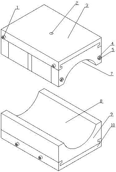
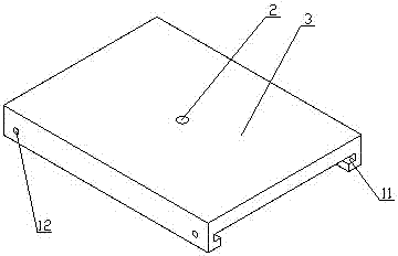
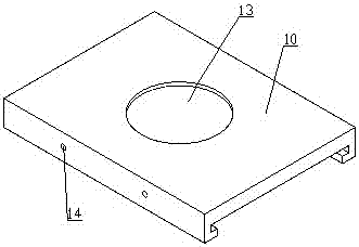
[0022] Such as Figure 1-Figure 6 The basic mechanical performance test device of the core-drilling method sample shown includes an upper connecting seat 3 and a lower connecting seat 10 with a rectangular cross section. The upper middle of the upper connecting seat 3 is provided with a bolt connecting with the lower part of the beam of the testing machine Connect the screw hole 2, the lower part of the lower connecting seat 10 is provided with a circular connecting groove 13 for nested connection with the lower hinge support of the testing machine; the upper connecting seat 3 is provided with an upper pressing seat, and the upper pressing The lower side of the seat is provided with an arc-shaped upper pressurizing groove 7 that is used to fit the outer wall of the core-drilling method sample and penetrates left and right. The upper side of the lower connecting seat 10 is provided with a lower pressurizing seat 9 and the upper side of the lower pressurizing seat 9 An arc-shaped lo


PUM


Abstract

The invention discloses a basic mechanical property testing device of a drill core sample and relates to a structure reinforcement detection device. The testing device comprises an upper connecting seat and a lower connecting seat, wherein a connecting screw hole is formed in the upper side of the upper connecting seat; a connecting groove is formed in the lower side of the lower connecting seat; an upper pressing seat is arranged on the lower side of the upper connecting seat; an upper pressing groove is formed in the lower side of the upper pressing seat; a lower pressing seat is arranged on the upper side of the lower connecting seat; a lower pressing groove is formed in the upper side of the lower pressing seat; T-shaped grooves are formed in the lower side of the upper connecting seat and the upper side of the lower connecting seat respectively, and T-shaped sliding seats matched with the T-shaped grooves are arranged on the upper pressing seat and the lower pressing seat respectively; the upper pressing seat comprises five pressing blocks; two connecting holes are formed in each pressing block; connecting screw rods are arranged in the connecting holes in a penetrating manner; and connecting nuts are arranged at the two ends of the connecting screw rods. The device has the advantages of being simple in construction, reasonable in structure, good in economy, simple in mounting, stable, simple and convenient to use, high in testing data precision and the like.

Description


Claims


Application Information

Patent Timeline
Owner HARBIN INST OF TECH AT WEIHAI
Why Eureka
Try Eureka