Microwave shielding clothes shielding efficiency testing system

A technology of shielding effectiveness and testing system, which is applied in the direction of measuring devices, measuring electrical variables, instruments, etc., can solve the problems of inconsistent shielding effectiveness, complex electromagnetic environment of shielding clothing, inaccurate data, etc., and achieves a large dynamic range of testing and saves testing cost, test precise effect

Pending Publication Date: 2017-07-11
NORTH CHINA ELECTRIC POWER UNIV (BAODING)
View PDF0 Cites 4 Cited by
  • Summary
  • Abstract
  • Description
  • Claims
  • Application Information

AI Technical Summary

Problems solved by technology

In an ideal state, E2E1, and the shielding effectiveness is negative. It is concluded that the field strength of the shielded clothing is stronger than that of the non-shielded clot

Method used


Image

  • Microwave shielding clothes shielding efficiency testing system

Examples


Example Embodiment

[0022] In order to avoid the influence of resonance on the negative shielding effectiveness of the test result, the present invention provides a microwave shielding suit shielding effectiveness test system. The present invention will be described in detail below with reference to the accompanying drawings.

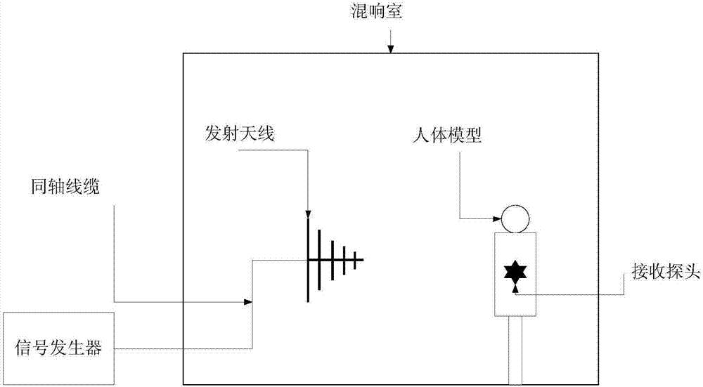
[0023] Attached figure 1 Schematic diagram of the structure of the shielding effectiveness test system for microwave shielding suits, such as figure 1 As shown, the system includes a reverberation room, a signal generator, a transmitting antenna, a human body model, and a receiving probe; the reverberation room is a shielded room constructed of highly reflective materials, and the reflectivity of the inner surface is generally higher than that of the shielded room. The receiving probe is placed inside the human body model, the transmitting antenna and the human body model are placed in the reverberation room, and the signal generator is connected to the transmitting antenna thro


PUM


Abstract

The invention belongs to the field of detecting the shielding effectiveness of microwave shielding clothing, in particular to a shielding effectiveness testing system for microwave shielding clothing. In order to solve the problem of inaccurate data in testing the shielding effectiveness of microwave shielding clothing in a resonance state, the invention provides a shielding effectiveness testing system for microwave shielding clothing. A shielding effectiveness testing system for microwave shielding clothing, comprising a reverberation chamber, a signal generator, a transmitting antenna, a human body model and a receiving probe. The invention tests the shielding effectiveness of the microwave shielding clothing by building a new controllable electromagnetic environment—a reverberation chamber. The test system does not need wave-absorbing materials and large power amplifiers, which saves testing costs. In addition, the device effectively avoids the influence of the negative shielding effectiveness on the test results in the resonance state, scientifically evaluates the shielding effectiveness of shielding microwave shielding clothing, and provides reasonable and scientific data for the evaluation of the shielding effectiveness of microwave shielding clothing.

Description


Claims


Application Information

Patent Timeline
Owner NORTH CHINA ELECTRIC POWER UNIV (BAODING)
Why Eureka
Try Eureka