Airflow distribution device for electrostatic-bag precipitator

A technology of air distribution device and dust collector, applied in the field of dust removal, can solve the problems of high damage rate of filter bags, poor effect of equalizing current, and no dust collection in cathode and anode in electrostatic precipitator area, so as to improve purification efficiency and reduce equipment failures. rate effect

Pending Publication Date: 2017-08-15
EQUIP MFG FACTORY HEBEI HONGDA ENVIRONMENT ENG CO LTD
View PDF0 Cites 1 Cited by
  • Summary
  • Abstract
  • Description
  • Claims
  • Application Information

AI Technical Summary

Problems solved by technology

However, in actual use, especially when the central inlet pipe is very irregular, the effect of flow equalization is very bad, resulting in local cathode and anode not collecting dust in the electrostatic precipitator area, and in the bag filter area due to local flow velocity too fast, the filter bag high breakage rate

Method used


Image

  • Airflow distribution device for electrostatic-bag precipitator
  • Airflow distribution device for electrostatic-bag precipitator
  • Airflow distribution device for electrostatic-bag precipitator

Examples


Example Embodiment

[0019] The technical solutions in the embodiments of the present invention will be clearly and completely described below in conjunction with the accompanying drawings in the embodiments of the present invention. Obviously, the described embodiments are only a part of the embodiments of the present invention, rather than all the embodiments. Based on the embodiments of the present invention, all other embodiments obtained by those of ordinary skill in the art without creative work shall fall within the protection scope of the present invention.

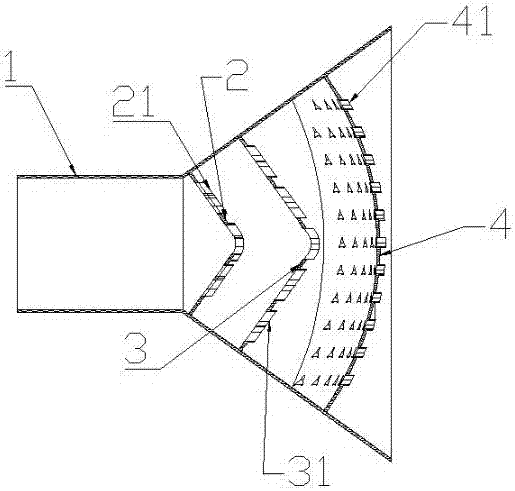
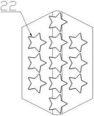
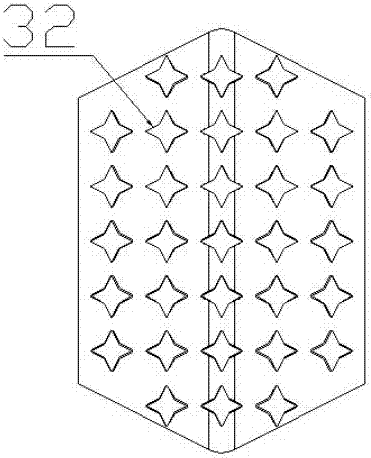
[0020] See Figure 1-4 , The present invention provides a technical solution: an air flow distribution device for an electric bag filter, comprising a housing 1, a first distribution plate 2, a second distribution plate 3, and a third distribution plate 4, the first distribution plate 2 , The second distribution plate 3 and the third distribution plate 4 are arranged in the housing 1 of the reducer from the outside to the inside. The upper


PUM


Abstract

The invention relates to an airflow distribution device of an electric bag dust collector, which includes a housing, a first distribution plate, a second distribution plate, and a third distribution plate. The first distribution plate, the second distribution plate, and the third distribution plate are from From the outside to the inside, they are arranged in the casing of the reducing pipe in sequence. The upper panels of the first distribution plate and the second distribution plate are at 90° to the upper panel of the casing, and the upper panels of the first distribution plate and the second distribution plate are The lower panel is 90° to the lower panel of the housing, the shape of the third distribution plate is spherical, and the opening ratios of the airflow holes on the first, second and third distribution plates are 40%, 60%, and 80% respectively , the shapes of the airflow holes on the first, second and third distribution plates are five-pointed star, four-pointed star and three-pointed star respectively. This kind of device adjusts the flow velocity of the inlet airflow in the variable diameter pipe, so that the airflow is evenly diffused and distributed, the purification efficiency is improved, and the failure rate of the equipment is reduced.

Description


Claims


Application Information

Patent Timeline
Owner EQUIP MFG FACTORY HEBEI HONGDA ENVIRONMENT ENG CO LTD
Why Eureka
Try Eureka