Display method and apparatus, and electronic device

A technology of electronic equipment and display method, which is applied to the protection of internal/peripheral computer components, etc., can solve the problem that the wide viewing angle display effect of electronic equipment is contrary to user needs, etc., and achieve the effect of improving privacy.

Pending Publication Date: 2017-10-03
BEIJING XIAOMI MOBILE SOFTWARE CO LTD
View PDF12 Cites 0 Cited by
  • Summary
  • Abstract
  • Description
  • Claims
  • Application Information

AI Technical Summary

Benefits of technology

This technology allows for control over how much viewable space on an image screen becomes visible when displaying different types or sizes of data. By adding a special type of material called a lenticular sheet behind it, this technology makes things look better without showing everything around them.

Problems solved by technology

The technical problem addressed in this patented technology relates how people who are watching TV on their screens can see other individuals or personal data without being able to read them out clearly due to privacy concerns associated therewith.

Method used


Image

  • Display method and apparatus, and electronic device
  • Display method and apparatus, and electronic device
  • Display method and apparatus, and electronic device

Examples


Embodiment Construction

[0058] Reference will now be made in detail to the exemplary embodiments, examples of which are illustrated in the accompanying drawings. When the following description refers to the accompanying drawings, the same numerals in different drawings refer to the same or similar elements unless otherwise indicated. The implementations described in the following exemplary examples do not represent all implementations consistent with the present disclosure. Rather, they are merely examples of apparatuses and methods consistent with aspects of the present disclosure as recited in the appended claims.

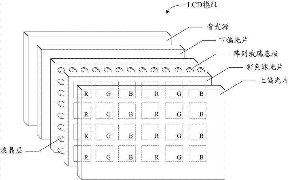
[0059] figure 1 It is a schematic diagram of the structure of the LCD display module, such as figure 1 As shown, the LCD display module can include: a backlight source, a lower polarizer, an array glass substrate, a liquid crystal layer, a color filter, and an upper polarizer; wherein, a red (R, red ), green (G, green), blue (B, blue) and other sub-pixels. Adjacent sub-pixels such as r


PUM


Abstract

The invention relates to a display method and apparatus, and an electronic device. The method is applied to the electronic device. A parallax barrier layer is arranged in front of a display component of the electronic device. The method comprises the steps of determining a display mode of the electronic device; when in a predefined private display mode, enabling the parallax barrier layer to form a parallax barrier located in a preset region; and, adjusting a content display mode of the display component to enable display contents in the preset region to be located in a visible region, corresponding to the parallax barrier, on the display component. Through the technical scheme, the content visible range of the electronic device can be controlled, so that the privacy of the electronic device is improved.

Description


Claims


Application Information

Patent Timeline
Owner BEIJING XIAOMI MOBILE SOFTWARE CO LTD
Why Eureka
Try Eureka