Cable peeling device

An optical cable and sheath technology, applied in the field of optical cable stripping devices, can solve problems such as low stripping efficiency, and achieve the effects of increasing practicability, facilitating replacement, and improving work efficiency

Inactive Publication Date: 2017-10-27
陈杨平
View PDF0 Cites 15 Cited by
  • Summary
  • Abstract
  • Description
  • Claims
  • Application Information

AI Technical Summary

Benefits of technology

In this patented technology there are technical features for creating better equipment used during opticals' inspections or maintenance operations. These improvements include improved performance over existing methods while also being easier to install on various locations without requiring excessive labor resources. Additionally, these devices have been designed specifically for specific types of opacities such as copper wires, plastic coatings, etc., making them more versatile than previous designs. Overall, they improve overall operational effectiveness and reduce cost-effectively compared to current solutions like manual cleaning techniques.

Problems solved by technology

This patented technical problem addressed in this patents relates to improving the quality control during production processes for making high-quality optically transmitting signals over long distances without sacrifices being made on material costs. Current methods involve hand cutting off the jacket from each end before pulling out another part, resulting in wasted materials due to human error. Therefore, new ways have been developed to automate these steps while maintaining consistently productivity levels.

Method used


Image

  • Cable peeling device
  • Cable peeling device
  • Cable peeling device

Examples


Embodiment Construction

[0029] The following will clearly and completely describe the technical solutions in the embodiments of the present invention with reference to the accompanying drawings in the embodiments of the present invention. Obviously, the described embodiments are only some, not all, embodiments of the present invention. Based on the embodiments of the present invention, all other embodiments obtained by persons of ordinary skill in the art without making creative efforts belong to the protection scope of the present invention.

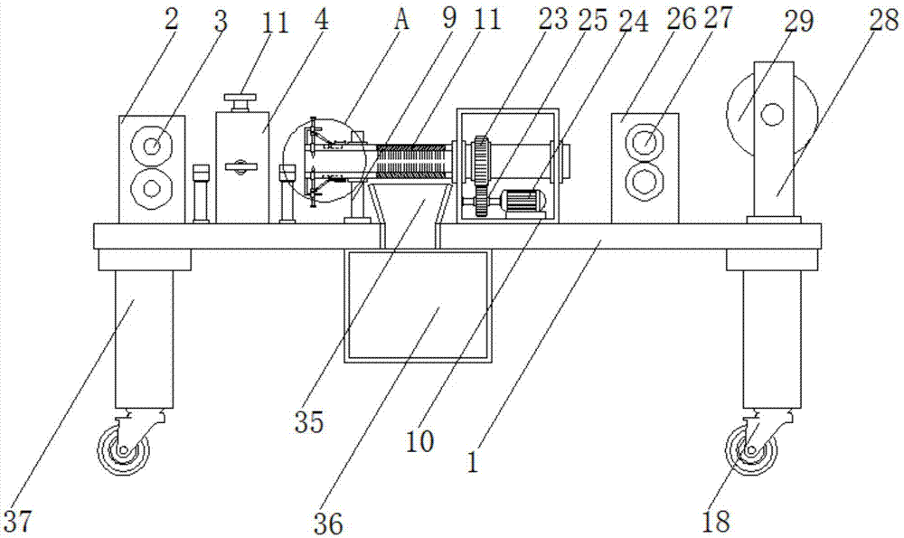
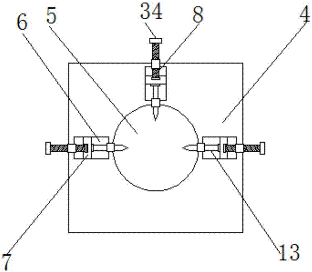
[0030] see Figure 1-6, the present invention provides a technical solution: an optical cable stripping device, including a bottom plate 1, a first fixed plate 2 is fixedly installed on the left side of the bottom plate 1, and the two first fixed plates 2 rotate between Connected with the first rotating roller 3; on the top of the bottom plate 1 and on the right side of the first fixed plate 2, a cutting block 4 is fixedly installed, and the center of the cutting


PUM


Abstract

The invention discloses a cable peeling device, which relates to the technical field of cable recovery. The cable peeling device comprises a bottom plate, wherein first fixed plates, a cutting block, a second fixed plate and a motor box are installed on the bottom plate from left to right in sequence; a first rotation roller is rotatably connected between the first fixed plates; the center of the cutting block is provided with a round cutting groove; the cutting block is also provided with a plurality of first cutting knives; the first cutting knives are installed along the radius direction of the cutting groove and can move along the radius direction of the cutting groove; a cutting cylinder is rotatably connected in the second fixed plate; one end of the cutting cylinder is provided with a second cutting knife; one end of the cutting cylinder penetrates through the motor box; the motor box provides rotation power for the cutting cylinder. According to the design, the cable can be continuously peeled, working efficiency is improved, in addition, the device automatically operates, manpower is reduced, and cost is reduced.

Description


Claims


Application Information

Patent Timeline
Owner 陈杨平
Why Eureka
Try Eureka