Capacitance detection circuit and capacitance detection method
A capacitance detection and circuit technology, used in instruments, static indicators, etc., can solve the problem that the bare glass panel cannot test the capacitance value, and achieve the effect of avoiding scrap, reducing waste and reducing costs.
- Summary
- Abstract
- Description
- Claims
- Application Information
AI Technical Summary
Benefits of technology
Problems solved by technology
Method used
Image

Examples
Embodiment 1
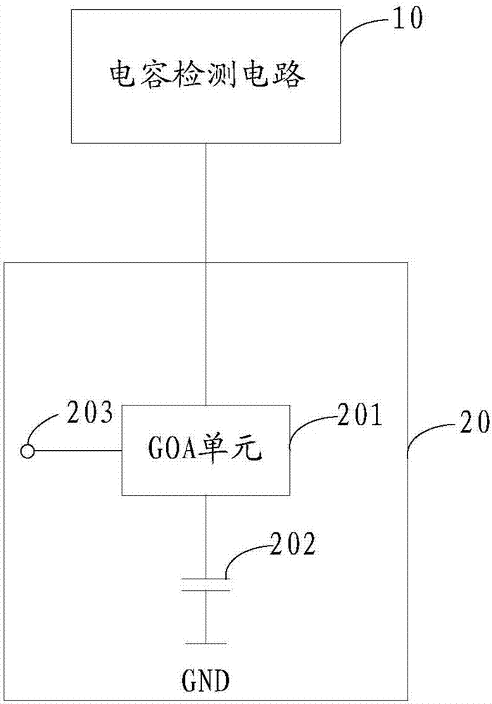
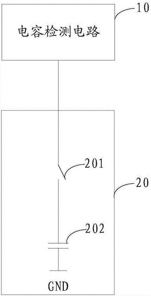
[0048] refer to figure 1 , shows a capacitance detection circuit provided by an embodiment of the present invention. The capacitance detection circuit 10 is used to detect the capacitance value of the bare glass panel 20, and the bare glass panel 20 includes a correspondingly connected GOA unit 201 and a panel capacitance 202;
[0049] When detecting the capacitance value of the bare glass panel 20, the capacitance detection circuit 10 is connected to the GOA unit 201, and the GOA unit 201 is connected to the signal input terminal 203;
[0050] The GOA unit 201 receives the signal input by the signal input terminal 203 and turns on, the capacitance detection circuit 10 charges and discharges the panel capacitance 202 to obtain the charging voltage of the panel capacitance 202, and according to the panel The charging voltage of the capacitor 202 is used to calculate and output the capacitance value of the panel capacitor 202 .
[0051] In this embodiment, the bare glass panel 20
Embodiment 2
[0078] A capacitance detection circuit provided by an embodiment of the present invention. The capacitance detection circuit 10 is used to detect the capacitance value of the bare glass panel 20, and the bare glass panel includes a plurality of GOA units 2011, 2012, 2013 and a plurality of panel capacitances 2021, 2022, 2023 connected correspondingly;
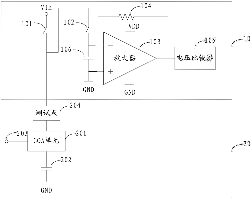
[0079] The capacitance detection circuit 10 is connected to a plurality of GOA units 2011, 2012, 2013 through a test point 204;
[0080] Each GOA unit is connected to the clock signal terminal CLK; the first level GOA unit 2011 is connected to the initial trigger signal terminal STV1; the output terminal Out of the previous level GOA unit is connected to the trigger signal input terminal STV of the next level GOA unit; the next level The output terminal Out of the GOA unit is connected to the reset terminal Reset of the upper-level GOA unit;
[0081] The GOA unit of the previous level is turned on after receiving the trigger sign
Embodiment 3
[0088] refer to Figure 8 , shows a flowchart of steps of a capacitance detection method provided by an embodiment of the present invention. Applied to the capacitance detection circuit described in Embodiment 1 to Embodiment 2, the method includes:
[0089] In step 301, the GOA unit is turned on when the clock signal jumps to a high level after receiving a high level trigger signal.
[0090] In this embodiment, the GOA unit is controlled by a trigger signal and a clock signal, see Figure 5 and Figure 7 , the GOA unit receives a high-level trigger signal STV, and turns on when the clock signal CLK jumps to a high level. The first level GOA unit 2011 receives the initial trigger signal STV1.
[0091] Step 302 , the capacitance detection circuit charges and discharges the panel capacitance, obtains the charging voltage of the panel capacitance, and calculates and outputs the capacitance value of the panel capacitance according to the charging voltage of the panel capacitance.
PUM
 Abstract
Description
Claims
Application Information
 - R&D Engineer
- R&D Manager
- IP Professional
- Industry Leading Data Capabilities
- Powerful AI technology
- Patent DNA Extraction
Browse by: Latest US Patents, China's latest patents, Technical Efficacy Thesaurus, Application Domain, Technology Topic.
© 2024 PatSnap. All rights reserved.Legal|Privacy policy|Modern Slavery Act Transparency Statement|Sitemap