Mounting-free and rapidly-dismounted road guardrail
An installation-free and road-free technology, applied to roads, roads, road signs, etc., can solve the problems of high rigidity of the isolation guardrail, casualties in the vehicle, and inconvenient road maintenance of the isolation guardrail, so as to reduce the risk of collision rebound, improve safety, The effect of alleviating the stress of traffic jams
- Summary
- Abstract
- Description
- Claims
- Application Information
AI Technical Summary
Benefits of technology
Problems solved by technology
Method used
Image

Examples
Embodiment 1
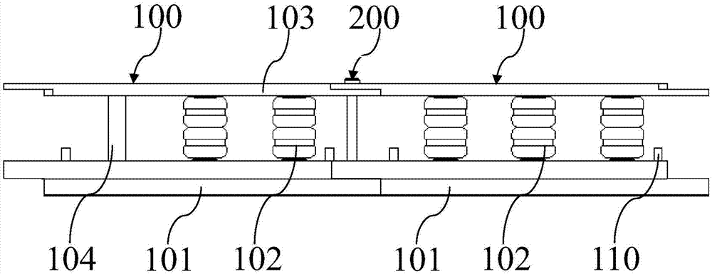
[0042] Such as Figure 1 to Figure 6 As shown, an installation-free quick-release road guardrail of the present invention is arranged on the central line of the road or on the side of the road, and includes several component units 100, and two adjacent component units 100 are connected by pin shafts 200, and the component units 100 include The elastic rotating body 102 and the guardrail body 101, the guardrail body 101 includes circular arc plates 108 arranged symmetrically, the guardrail body 101 is in the shape of "several", the guardrail body 101 is provided with tubular supports 104 at intervals, and the elastic rotating body 102 is rotatably combined with the tubular support 104, the upper part of the tubular support 104 is horizontally equipped with a crossbar 103, the two ends of the guardrail body 101 and the crossbar 103 are provided with connecting pin holes, and the pin shaft 200 is inserted into the connecting pin hole The adjacent guardrail body 101 and the horizonta
Embodiment 2
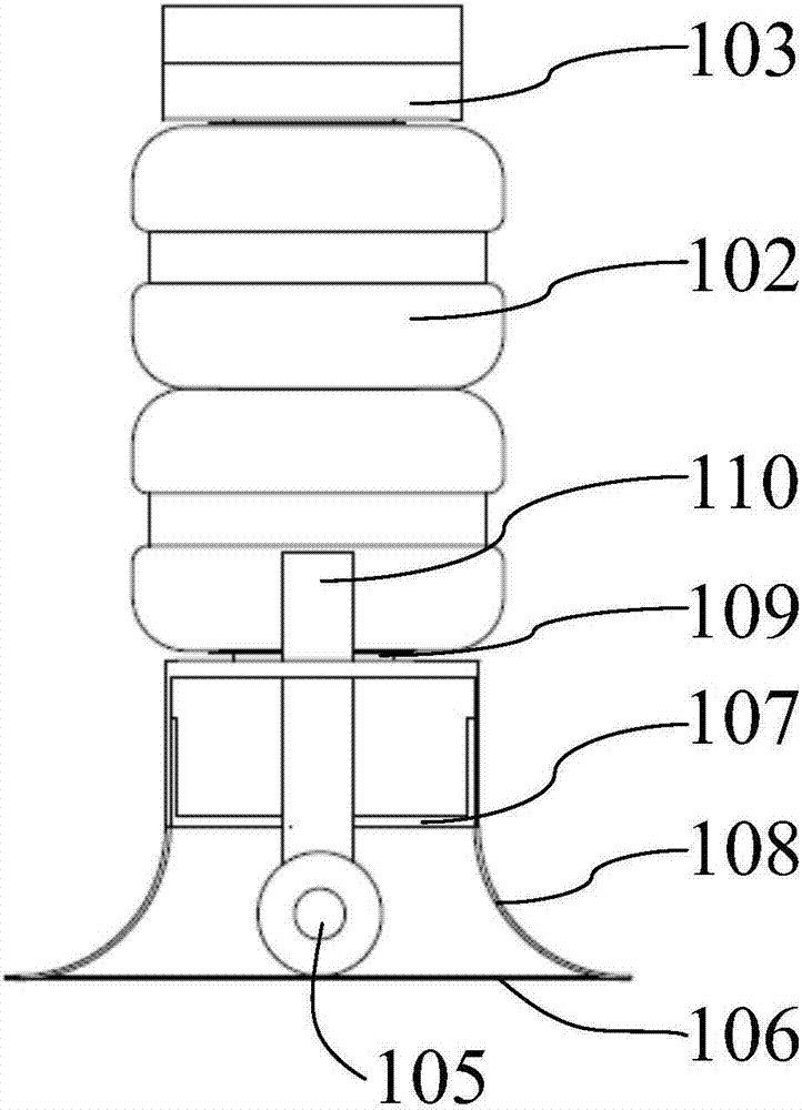
[0050] Such as Figure 6 As shown, the elastic rotating body 102 is one of the important parts of the present invention. The elastic rotating body 102 includes a column body 1021 and a rotation support tube 1022. The column body 1021 has a through hole passing through the column body 1021 from its upper part to the bottom part. In the through hole of the body 1021.
[0051] The elastic rotating body 102 is made of elastic material as a whole. On the one hand, the rigidity of the contact part with the tubular support 104 is not enough, so it is easy to increase the friction with the tubular support 104. On the other hand, due to the elasticity of the elastic rotating body 102 Deformation, tightly wrapped on the tubular support 104, cannot rotate due to the existence of deformation, and cannot achieve the effect of absorbing impact force and guiding. Rotating the support tube enhances the strength of the elastic rotating body 102 to achieve free rotation.
[0052] In the isolatio
Embodiment 3
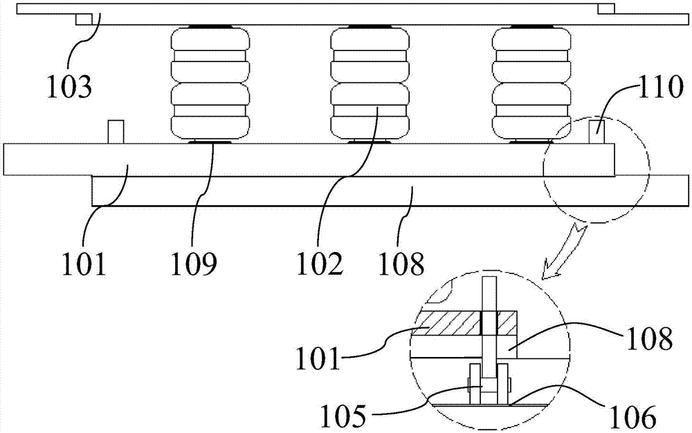
[0054] exist image 3 , it can be seen that the assembly unit 100 also includes a rotating receiving member 109 sleeved on the tubular support 104 and arranged between the guardrail body 101 and the elastic rotating body 102, reducing the distance between the guardrail body 101 and the elastic rotating body 102. The friction effect helps the elastic rotating body 102 to rotate normally and guide the vehicle to return to the correct vehicle.
[0055] During the use of the present invention, the rotating receiving member 109 includes two turning circles, and the two turning circles are mutually rotatable. By setting the two turning circles, the upper turning circle is in contact with the elastic rotating body 102, and the lower turning circle is in contact with the guardrail body 101. , the frictional force between the upper turning circle and the lower turning circle is smaller, which ensures the free rotation of the elastic rotating body 102 .
[0056] The two slewing rings are
PUM
| Property | Measurement | Unit |
|---|---|---|
| Arc radius | aaaaa | aaaaa |
Abstract
Description
Claims
Application Information
 - R&D Engineer
- R&D Manager
- IP Professional
- Industry Leading Data Capabilities
- Powerful AI technology
- Patent DNA Extraction
Browse by: Latest US Patents, China's latest patents, Technical Efficacy Thesaurus, Application Domain, Technology Topic.
© 2024 PatSnap. All rights reserved.Legal|Privacy policy|Modern Slavery Act Transparency Statement|Sitemap