Synchronous denitrification reactor

A denitrification and reactor technology, applied in chemical instruments and methods, anaerobic digestion treatment, biological water/sewage treatment, etc., can solve the problems of high project investment and equipment investment, and achieve low equipment investment and simple operation control , the effect of reducing the floor area

Pending Publication Date: 2017-12-15
喻昌勇
View PDF4 Cites 1 Cited by
  • Summary
  • Abstract
  • Description
  • Claims
  • Application Information

AI Technical Summary

Benefits of technology

In this new technology that uses bacteria called Activated Sludges (AS) instead of traditional nitrogen-based methods like ammonium or urethane, it allows better removal from harmful substances such as organics and pesticides while also reducing their concentrations in water bodies without requiring expensive treatment facilities. It can be installed easily with minimal space requirements compared to current technologies used by other types of treatments.

Problems solved by technology

Technics Problem addressed in this patents include reducing nitroso substances present in septic tanks without affecting their ability to reduce NOx levels due to incomplete reduction caused by traditional methods like ABOX® systems used during conventional treatments such as activatedsludges. Additionally, there may also exist issues related to improving the performance of these techniques when applied at different stages of purifications depending upon factors like pH level and temperature.

Method used


Image

  • Synchronous denitrification reactor
  • Synchronous denitrification reactor
  • Synchronous denitrification reactor

Examples


Embodiment Construction

[0038] The technical solutions of the present invention will be further described below in conjunction with the accompanying drawings and through specific implementation methods.

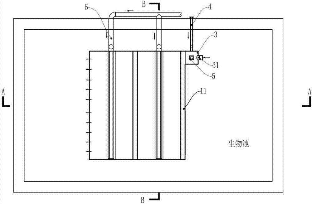
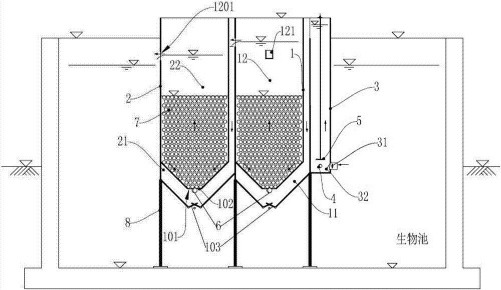
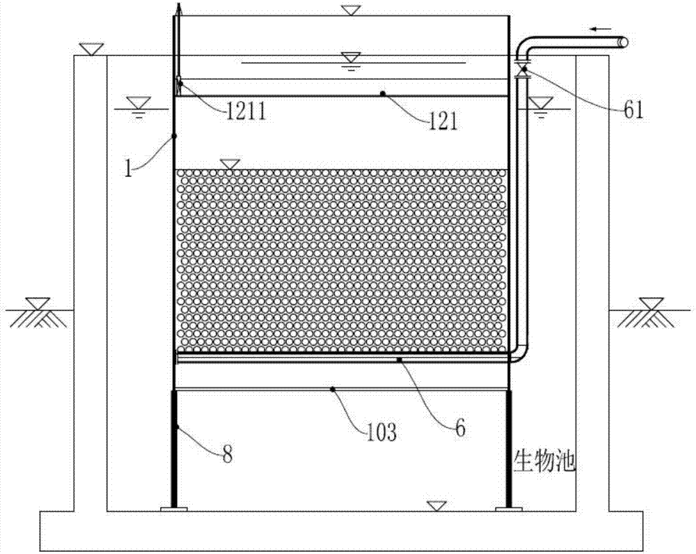
[0039] A synchronous denitrification reactor, comprising a first-stage reaction box 1, a second-stage reaction box 2, an inlet water mixing box 3, a carbon source feeding pipe 4, a mixing agitator 5, a backwashing water pipe 6, and a spherical packing 7;

[0040] The first-order reaction box 1 and the second-order reaction box 2 are connected in series;

[0041] The first-stage reaction tank 1 includes a first water distribution oxygen release chamber 11 and a first denitrification chamber 12;

[0042] The second-stage reaction tank 2 includes a second water distribution oxygen release chamber 21 and a second denitrification chamber 22;

[0043] The bottoms of the first denitrification chamber 12 and the second denitrification chamber 22 are conical, and the bottoms of the first denitrification chambe


PUM


Abstract

The invention discloses a synchronous denitrification reactor. The synchronous denitrification reactor comprises a first order reaction chamber, a second order reaction chamber, a inlet water mixing chamber, a carbon source adding pipe, a mixing stirring device, a backwash water pipe, and a spherical filling material; the first order reaction chamber and the second order reaction chamber are connected in series; the first order reaction chamber comprises a first water preparation oxygen release chamber and a fist denitrification chamber; the second order reaction chamber comprises a second water preparation oxygen release chamber and a second denitrification chamber; the bottoms of the first denitrification chamber and the second denitrification chamber are designed to be tapered; the bottom of the first denitrification chamber is provided with a hole; the bottom of the second denitrification chamber is provided with a hole; the outside edge of each of the holes is covered with filling material blocking screen; and the spherical filling material is injected into the first denitrification chamber and the second denitrification chamber. According to the synchronous denitrification reactor, synchronous denitrification anoxic conditions are achieved in an aerobic tank or an anoxic pool via insulation, biomembrane loaded with the spherical filling material is used for reaction of nitrates and nitrites in backflow sewage with the added carbon source, and generated nitrogen overflow, so that denitrification is realized.

Description


Claims


Application Information

Patent Timeline
Owner 喻昌勇
Why Eureka
Try Eureka