Concrete mixing and transporting vehicle motor

A technology for mixing and conveying vehicles and concrete, which is applied in the direction of collectors, electromechanical devices, electric vehicles, etc., can solve the problem of generating a large amount of exhaust gas, and achieve the effect of improving power density, improving safety and stability, and avoiding the phenomenon of vehicle runaway.

Inactive Publication Date: 2017-12-19
刘志运
View PDF0 Cites 0 Cited by
  • Summary
  • Abstract
  • Description
  • Claims
  • Application Information

AI Technical Summary

Benefits of technology

This patented technology allows for efficient utilization of batteries during long periods without losing their effectiveness or causing damage from overheated equipment. It achieves this through multiple ventilated systems made up of different parts connected together. Additionally, there're no increased size required because they form part of one single unit instead of two separate units. Overall, these technical improvements help prevent accidents such as engine failures while maintaining high performance levels on road transport vehicles like cement mixers.

Problems solved by technology

This patented technical problem addressed by this patents relates to improving the efficiency at driving heavy loads used in civil engineering projects such as road building materials or demolition tools. However, current methods require accurate detection of the work status of motors with smaller sizes but requiring more powerful engines than usual.

Method used


Image

  • Concrete mixing and transporting vehicle motor

Examples


Embodiment 1

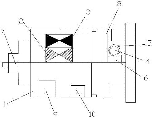
[0018] A concrete mixer truck motor, including a housing 1, a stator 2, a rotor 3, a fan 4, a wind cover 5 and a battery 6, a rotating shaft 7 is arranged in the middle of the housing 1, and the stator 2 is arranged on the rotor 3 Outside, one end inside the housing 1 is provided with a partition 8, one side of the partition 8 is provided with the fan 4, and the other side of the partition 8 is provided with the stator 2 and the rotor 3. The windshield 5 is arranged on the outside of the fan 4, the battery 6 is arranged below the fan 4, and the outer wall of the casing 1 is radially distributed with heat dissipation ribs, and the heat dissipation ribs are arranged radially Distributed at intervals, the heat dissipation ribs are covered with an outer cover plate, the outer cover plate is provided with heat dissipation grooves and heat dissipation holes, the heat dissipation grooves are provided with heat dissipation fins, and the heat dissipation fins and the heat dissipation holes

Embodiment 2

[0021] A concrete mixer truck motor, including a housing 1, a stator 2, a rotor 3, a fan 4, a wind cover 5 and a battery 6, a rotating shaft 7 is arranged in the middle of the housing 1, and the stator 2 is arranged on the rotor 3 Outside, one end inside the housing 1 is provided with a partition 8, one side of the partition 8 is provided with the fan 4, and the other side of the partition 8 is provided with the stator 2 and the rotor 3. The windshield 5 is arranged on the outside of the fan 4, the battery 6 is arranged below the fan 4, and the outer wall of the housing 1 is radially distributed with cooling ribs, and the outer wall of the cooling rib is covered with a cover The outer cover plate is provided with heat dissipation grooves and heat dissipation holes, the heat dissipation grooves are provided with heat dissipation fins, and the heat dissipation fins and the heat dissipation holes are arranged in a dislocation manner.

[0022] The inside of the housing is also provid


PUM


Abstract

The invention relates to a concrete mixer truck motor, which includes a casing, a stator, a rotor, a fan, a wind cover and a storage battery. A rotating shaft is arranged in the middle of the casing, the stator is arranged outside the rotor, and the casing is A baffle is provided at one end of the baffle, the fan is provided on one side of the baffle, the stator and the rotor are provided on the other side of the baffle, and the windshield is provided outside the fan, The storage battery is arranged below the fan, and heat dissipation ribs are radially distributed on the outer wall of the housing. The heat dissipation ribs are covered with an outer cover plate, and the outer cover plate is provided with heat dissipation grooves and heat dissipation holes. The heat dissipation grooves A cooling fin is arranged in the center, and the cooling fin is arranged in a dislocation manner with the cooling hole. The motor designed by the invention can effectively avoid the occurrence of circuit burnout caused by excessive temperature, thereby greatly improving the safety and stability of the concrete mixer truck.

Description


Claims


Application Information

Patent Timeline
Owner 刘志运
Why Eureka
Try Eureka