Synchronous permanent magnet motor machining device for centrifugal blowers

A permanent magnet motor and processing device technology, applied in auxiliary devices, metal processing equipment, manufacturing tools, etc., can solve the problems of cumbersome clamping and replacement of synchronous permanent magnet motor tools, no anti-collision function, and low degree of automation , to avoid the phenomenon of collision, improve the degree of automation and reduce labor intensity

Inactive Publication Date: 2017-12-29
王彩英
View PDF0 Cites 0 Cited by
  • Summary
  • Abstract
  • Description
  • Claims
  • Application Information

AI Technical Summary

Problems solved by technology

[0003] In order to solve the above problems, the present invention provides a centrifugal blower synchronous permanent magnet motor processing device, which can solve the problem that in the manufacturing process of synchronous permanent magnet motors, the general processing device has a low degree of automation, thereby greatly increasing people's labor. Intensity, and some synchronous permanent magnet motors are more cumbersome to clamp and replace the tool during processing, and even some synchronous permanent magnet motor processing devices do not have the problem of anti-collision function

Method used


Image

  • Synchronous permanent magnet motor machining device for centrifugal blowers
  • Synchronous permanent magnet motor machining device for centrifugal blowers
  • Synchronous permanent magnet motor machining device for centrifugal blowers

Examples


Example Embodiment

[0018] In order to make it easy to understand the technical means, creative features, objectives and effects achieved by the present invention, the present invention will be further explained below in conjunction with specific drawings.

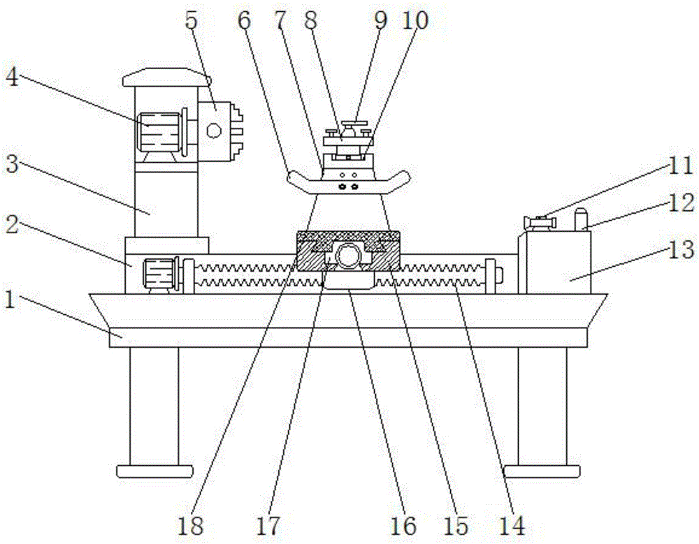
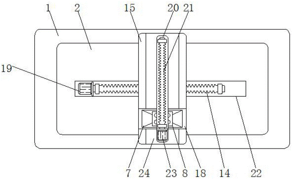
[0019] Such as Figure 1 to Figure 4 As shown, a centrifugal blower synchronous permanent magnet motor processing device includes a device frame 1, a processing base 2, a column 3, a transverse screw 14 and a longitudinal placement cavity 20, and a processing base 2 is fixed at the center of the top of the device frame 1 , A column 3 is installed on the top side of the processing base 2, and a rotating motor 4 is installed inside the column 3 through a support plate. The model of the rotating motor 4 can be Y90L-2. The outer wall of the column 3 at the position of the rotating motor 4 is hinged with three The chuck 5 and the three chuck 5 are connected to the output end of the rotating motor 4 through a coupling. The center of the top of the proces


PUM


Abstract

The invention relates to a centrifugal blower synchronous permanent magnet motor processing device, which includes a device frame, a processing base, a column, a horizontal screw and a longitudinal placement cavity. A processing base is fixed at the center of the top of the device frame. A column is installed on one side, and a rotating motor is installed inside the column through a support plate. A three-grip chuck is hinged on the outer wall of the column at the position of the rotating motor. A waste collection cover is provided at the center of the body surface, studs are provided on the side walls at both ends of the waste collection cover, and a rotating cavity is provided at the center of the top of the tool rest support body. A knife rest disc is provided, and a rotary table is installed at the bottom end of the knife rest disc. The invention not only improves the working efficiency of the processing device, improves the convenience of the tool changing process of the processing device, but also avoids the collision phenomenon of the processing device.

Description


Claims


Application Information

Patent Timeline
Owner 王彩英
Why Eureka
Try Eureka