Floor drain

A floor drain and shell technology, applied in waterway systems, climate change adaptation, drainage structures, etc., can solve problems such as affecting the normal drainage of floor drains, being easily blocked by impurities such as hair, and being difficult to remove, and achieving convenient replacement, easy separation, and low cost. Effect

Inactive Publication Date: 2018-01-09
JIANGYIN TONGQI HARDWARE ELECTRICAL APPLIANCE FACTORY
View PDF0 Cites 0 Cited by
  • Summary
  • Abstract
  • Description
  • Claims
  • Application Information

AI Technical Summary

Problems solved by technology

[0002] The floor drain is widely used as a drainage component used in bathrooms, kitchens and other places. Because the discharged water may contain impurities such as hair and dust, a mesh separation cover is generally installed on the top of the floor drain to achieve For the separation of the aforementioned impurities, but after a short period of use, the mesh surface of the separation cover is easily blocked by impurities such as hair, which affects the normal drainage of the normal floor drain, and the hair is usually tough and difficult to remove

Method used


Image

  • Floor drain

Examples


Example Embodiment

[0018] The present invention will now be described in further detail with reference to the drawings. These drawings are all simplified schematic diagrams, which merely illustrate the basic structure of the present invention in a schematic manner, so they only show the structures related to the present invention.

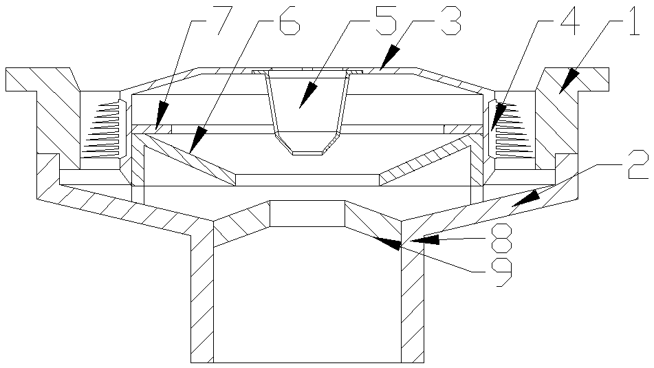
[0019] Such as figure 1 As shown, the present invention is a floor drain, including a mounting ring, a drain pipe is connected to the lower end of the mounting ring through a tapered tube, and a support is coaxially fixed on the inclined inner wall of the tapered tube Ring, a drainage opening is further provided at the fixed position of the support ring and the inner wall of the reducer; a separation assembly is connected to the support ring, and the separation assembly includes a cylindrical separation housing, the separation housing The bottom of the separation shell is an open structure, and a high-speed separator is provided in the middle of the closed end of the sepa


PUM


Abstract

The invention relates to a floor drain comprising a support ring; a lower end of the support ring is connected with a water drainage pipe through a reducing pipe; a support ring is coaxially fixed onan inclined inner wall of the reducing pipe; a draining opening is installed at a fixing position of the support ring and the reducing pipe; a separating member is connected to the support ring; the separating member comprises a cylindrical separating housing; a bottom of the separating housing is an opening structure; a high-speed separator is installed at the middle part of a sealed end of the separating housing; the high-speed separator comprises a cylindrical separating filter screen with an opening on the top; filler made of porous material is installed inside the separating filter screen; the opening end at the top of the filter screen is fixed at the middle part of the sealed end of the separating housing; multiple draining openings corresponding to the openings on the top of the filter screen are installed at the middle part of the sealed end; a low-speed separator is installed at an outer side wall of the separating housing; the low-speed separator comprises a connecting ringwhich is fixed on an outer side wall of the separating housing; the outer side wall of the connecting wall is provided with multiple separating thorn rings in an array mode.

Description


Claims


Application Information

Patent Timeline
Owner JIANGYIN TONGQI HARDWARE ELECTRICAL APPLIANCE FACTORY
Why Eureka
Try Eureka