Plate conveying device of plate punching equipment

A technology of punching equipment and conveying devices, which is applied in the direction of conveyor control devices, conveyor objects, transportation and packaging, etc., can solve the problems of difficult to guarantee the quality of punching, uneven levels of workers, and high labor intensity of workers. Achieve the effects of reducing labor intensity of workers, improving positioning accuracy, and improving punching quality

Inactive Publication Date: 2018-01-12
ZHEJIANG YUEQIANG FURNITURE TECH CO LTD
View PDF0 Cites 2 Cited by
  • Summary
  • Abstract
  • Description
  • Claims
  • Application Information

AI Technical Summary

Benefits of technology

This technology allows for precise movement of plates during production without requiring manual adjustment or repositioning them manually. By utilising a special device called a chain driving system that moves one part (the rotor) while another part holds it securely, this ensures stable conveyance over long distances. Additionally, sensors can be added inside the machine's structure to help track if any defective parts have entered into your circuitry. Overall, these technical featings make the process more efficient and reliable than previous methods like hand-placement.

Problems solved by technology

The technical problem addressed in this patented technology relating to improving the accuracy and consistency with which furniture components can be installed during manufacturing processes while reducing human error factors like manual assembly process steps or inspections that may affect their final product's performance.

Method used


Image

  • Plate conveying device of plate punching equipment
  • Plate conveying device of plate punching equipment
  • Plate conveying device of plate punching equipment

Examples


Embodiment Construction

[0015] The present invention will be further described below in conjunction with the accompanying drawings and embodiments, but not as a basis for limiting the present invention.

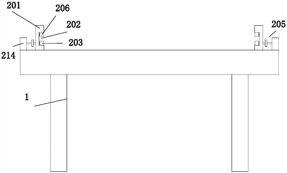
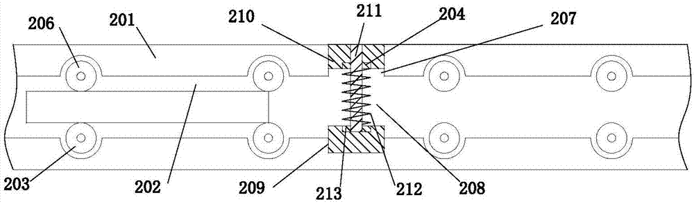
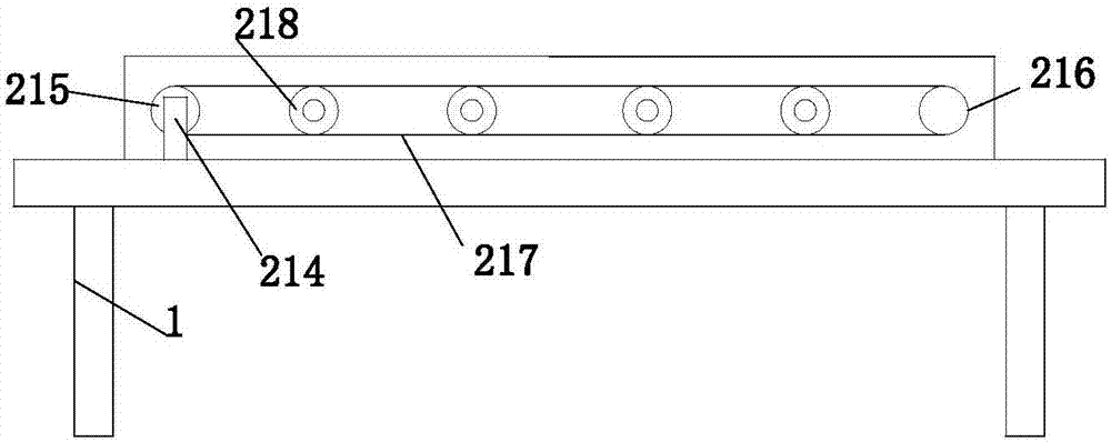
[0016] Example. A sheet material conveying device of sheet material punching equipment, constituted as figure 1 and Figure 4 As shown, including the frame 1, the frame 1 is provided with two guide rails 201 arranged in parallel front and rear, the inner surface of each guide rail 201 is provided with a chute 202, and the bottom end of the chute 202 is provided with a group of driving rollers 203, The top inside the chute 202 is provided with a group of driven pressing rollers 206; the driving roller 203 is connected with a chain drive mechanism 205 located on the outer side of the guide rail 201 via a rotating shaft; the chute 202 is also provided with a positioning opening 207 , the positioning opening 207 is provided with a positioning mechanism 208 .

[0017] The positioning mechanism 208 includ


PUM


Abstract

The invention discloses a plate conveying device of plate punching equipment. The plate conveying device comprises a rack (1); two guide rails (201) which are arranged in a front-back parallel mode are arranged on the rack (1), and a sliding groove (202) is formed in the inner side face of each guide rail (201); a group of driving rolling wheels (203) are arranged at the bottom end of the interiorof each sliding groove (202), and a group of driven pressing rolling wheels (206) are arranged at the top end of the interior of each sliding groove (202); a chain driving mechanism (205) located onthe outer side face of each guide rail (201) is connected to the corresponding driving rolling wheels (203) through a rotating shaft; and a positioning opening (207) is further formed in each slidinggroove (202), and a positioning mechanism (208) is arranged on each positioning opening (207). The plate conveying device of the plate punching equipment has the beneficial effects that punching quality can be improved, and the labor intensity of workers is reduced.

Description


Claims


Application Information

Patent Timeline
Owner ZHEJIANG YUEQIANG FURNITURE TECH CO LTD
Why Eureka
Try Eureka