Multifunctional laser cutting robot with automatic feeding device

A laser cutting, automatic feeding technology, applied in laser welding equipment, welding equipment, metal processing equipment and other directions, can solve the problems of prolonging metal processing time, reducing production efficiency, spending a lot of time, etc., to expand the scope of use, reduce time, ease of use

Inactive Publication Date: 2018-01-16
戚新昂
View PDF0 Cites 3 Cited by
  • Summary
  • Abstract
  • Description
  • Claims
  • Application Information

AI Technical Summary

Problems solved by technology

[0002] Metal processing is an indispensable processing method in modern industry. When processing metal, corresponding steps such as engraving and cutting are required to meet the needs of users. In current metal processing, most It is not possible to carry out automati

Method used


Image

  • Multifunctional laser cutting robot with automatic feeding device
  • Multifunctional laser cutting robot with automatic feeding device
  • Multifunctional laser cutting robot with automatic feeding device

Examples


Embodiment Construction

[0023] The following will clearly and completely describe the technical solutions in the embodiments of the present invention with reference to the accompanying drawings in the embodiments of the present invention. Obviously, the described embodiments are only some, not all, embodiments of the present invention. Based on the embodiments of the present invention, all other embodiments obtained by persons of ordinary skill in the art without making creative efforts belong to the protection scope of the present invention.

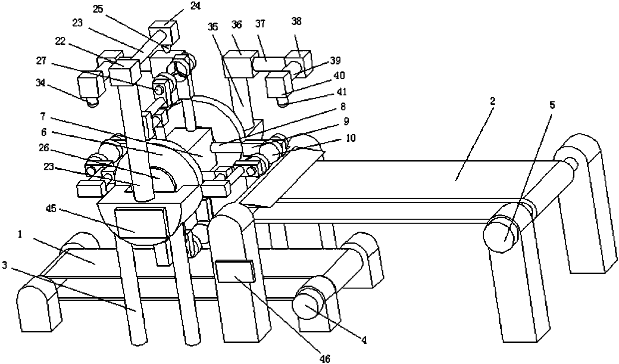
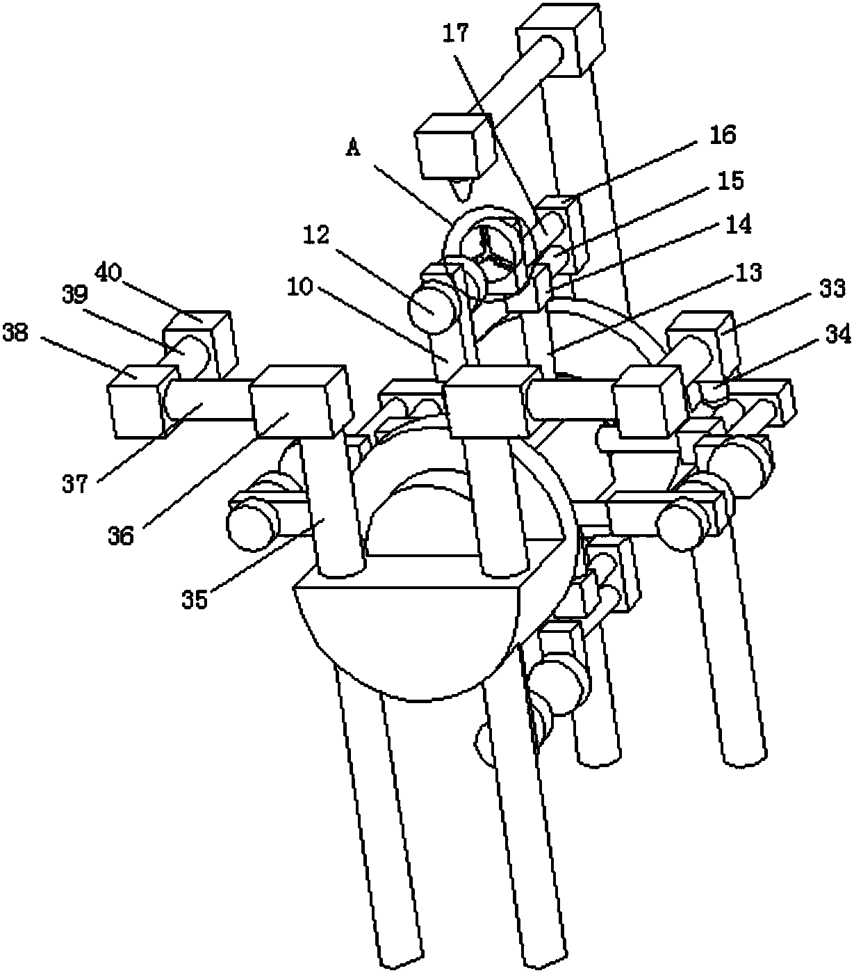
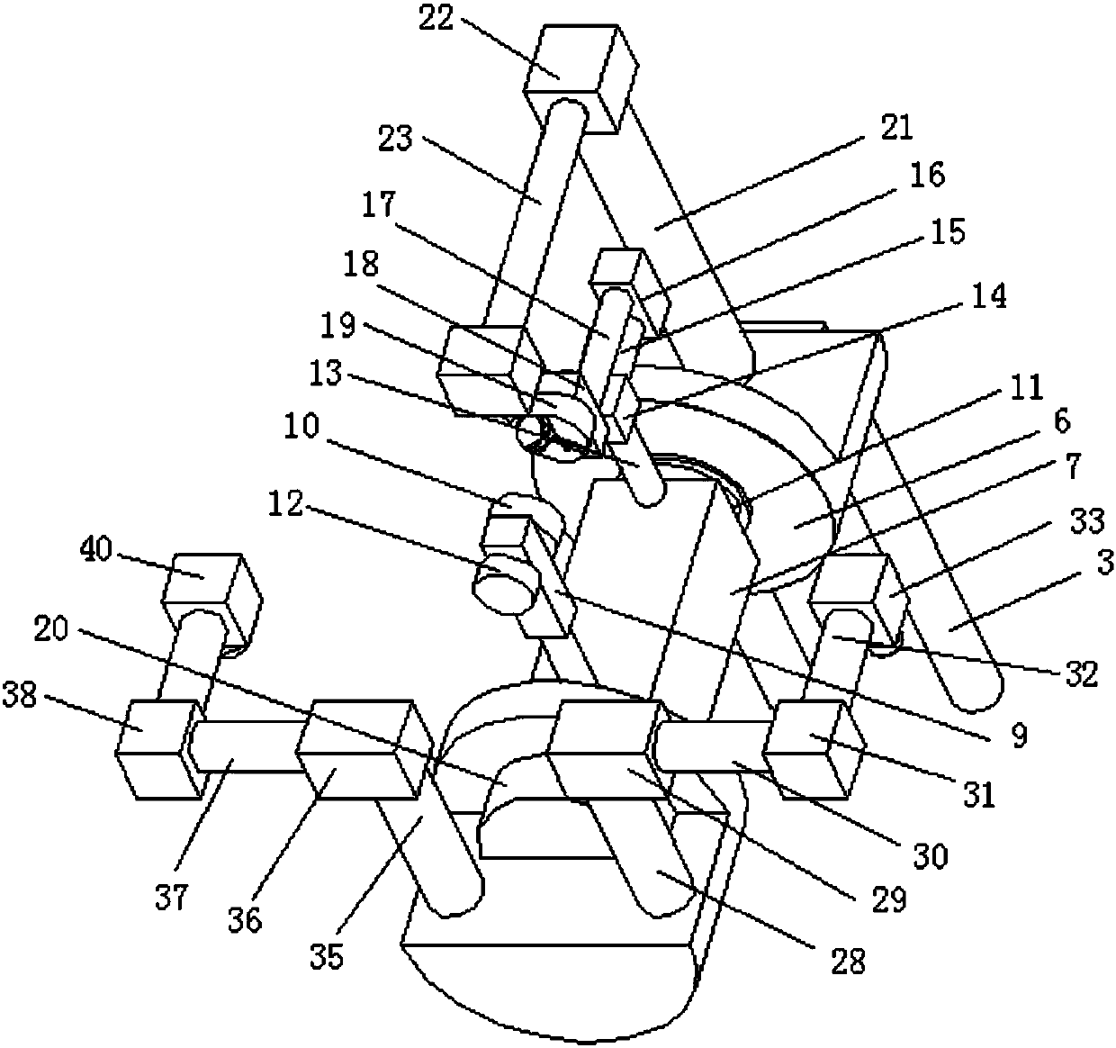
[0024] see Figure 1-4, the present invention provides a technical solution: a multifunctional laser cutting robot with an automatic feeding device, including a first conveying device (1), a second conveying device (2) and a cutting device (3), the first A conveying device (1) is arranged below the cutting device (3), the second conveying device (2) is arranged on the side of the cutting device (3), and the second conveying device (2) is positioned at the first c


PUM


Abstract

The invention discloses a multifunctional laser cutting robot with an automatic feeding device. The multifunctional laser cutting robot comprises a first conveying device, a second conveying device and a cutting device, the first conveying device is arranged below the cutting device, the second conveying device is arranged on the side face of the cutting device and is located above the first conveying device, the first conveying device and the second conveying device both comprise conveying belts and supports, and a first motor is arranged on the side face of the support of the first conveyingdevice. Through a PLC, by controlling work of the first motor through a frequency converter, a raw material which needs to be processed is conveyed to the corresponding position through the first conveying device, then the raw material is fixed through the first fixing device and the second fixing device, work of a third motor is controlled through the PLC and the frequency converter, the time needed for feeding is shortened, and a user conveniently uses the robot.

Description


Claims


Application Information

Patent Timeline
Owner 戚新昂
Why Eureka
Try Eureka