Power support tower with heat dissipation structure, and working method of power support tower

A technology of heat dissipation structure and tower, which is applied to towers, electrical components, substation/distribution device casings, etc., can solve the problems of limited use stability and heat dissipation performance, affecting applicability and practicability, and achieves compact and practical structure. Good performance and good stability

Inactive Publication Date: 2018-03-06
严白双
View PDF6 Cites 2 Cited by
  • Summary
  • Abstract
  • Description
  • Claims
  • Application Information

AI Technical Summary

Problems solved by technology

[0002] It is often necessary to set up power and communication towers on the roof for fixing and auxiliary support of various equipment, antennas, etc. Among them, some distribution boxes are often installed on the power towers to protect some main power consumption and power structures. Although the technical power tower can support and fix equipment, antennas, etc., its stability and heat dissipation performance are relatively limited, which will affect its applicability and practicability to a certain extent.

Method used


Image

  • Power support tower with heat dissipation structure, and working method of power support tower

Examples


Example Embodiment

[0019] Example 1

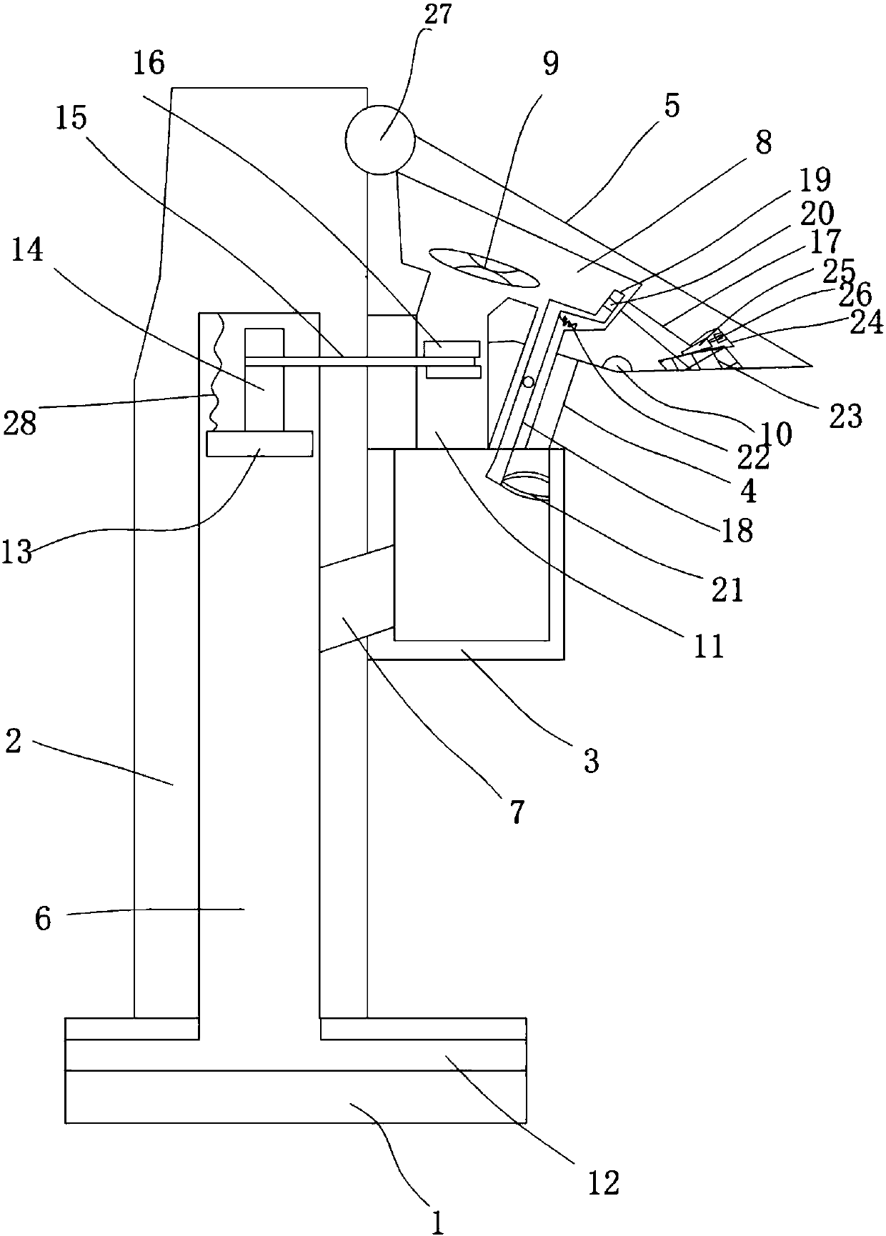
[0020] Such as figure 1 The illustrated power supporting tower with a heat dissipation structure includes a base 1, a tower main body 2 arranged on the base 1, and a power box 3 fixed on the tower main body 2, on the top of the power box 3 A vertical support rod 4 is provided, a top cover 5 is fixed on the top of the vertical support rod 4, a heat dissipation cavity 6 is provided in the tower main body 2, and a side wall of the tower main body 2 is provided with The inner cavity of the power box 3 is connected with a heat dissipation pipe 7 and one end of the heat dissipation pipe 7 extends into the heat dissipation cavity 6. An air cavity 8 is provided in the top cover 5, and an air cavity 8 is provided in the air cavity 8 The fan 9 and the power interface 10 connected to the fan 9, an air duct 11 connecting the air cavity 8 and the inner cavity of the power box 3 is provided in the vertical support rod 4, and the base 1 is provided with the The heat dissipatio


PUM


Abstract

The invention discloses a power support tower with a heat dissipation structure, and a working method of the power support tower. The power support tower comprises a pedestal, a tower main body disposed on the pedestal, and a power box fixed on the tower main body. The top surface of the power box is provided with a vertical rod, and the top of the vertical rod is fixedly provided with a top cover. The interior of the tower main body is provided with a heat dissipation cavity, and the interior of the top cover is provided with an air cavity. The interior of the vertical rod is provided with anair duct which is communicated with the air cavity and the inner cavity of the power box. The interior of the pedestal is provided with a heat dissipation channel communicated with the heat dissipation cavity. The interior of the heat dissipation cavity is provided with a heat dissipation piston plate, and an eccentric wheel is disposed between the heat dissipation piston plate and the top wall of the heat dissipation cavity. The eccentric wheel is provided with a rotating shaft rod, and the rotating shaft rod stretches out of a side wall of the tower main body and stretches into the air duct. The rotating shaft rod is provided with a blade, and the blade is located in the air duct. The power support tower is reasonable in structural setting, can achieve the supporting and fixing of powerequipment and a power-on structure, is better in heat dissipation performance and waterproof performance, is good in use stability, is high in adaptability, and is good in practicality.

Description


Claims


Application Information

Patent Timeline
Owner 严白双
Why Eureka
Try Eureka