Energy supply circuit for a lighting module

A lighting module and energy supply technology, which is applied to lighting devices, lighting and heating equipment, electric light sources, etc., can solve the problems of reduced service life of light sources, and achieve the effect of reducing loads

Active Publication Date: 2018-04-17
ZKW GRP GMBH
View PDF4 Cites 0 Cited by
  • Summary
  • Abstract
  • Description
  • Claims
  • Application Information

AI Technical Summary

Problems solved by technology

This is particularly disadvantageous, since the service life of the light source generally decreases as the operating temperature increases

Method used


Image

  • Energy supply circuit for a lighting module
  • Energy supply circuit for a lighting module

Examples


Embodiment Construction

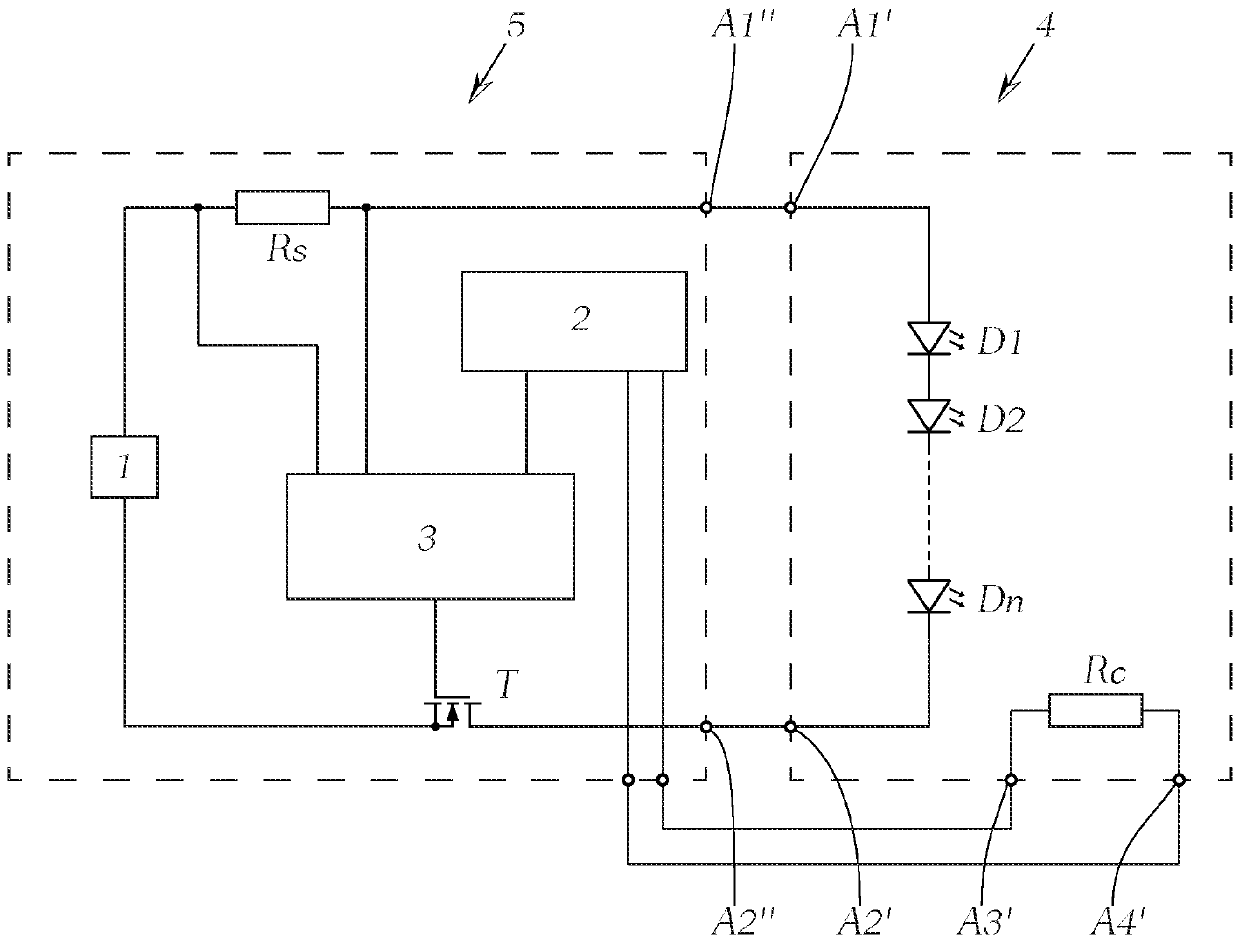
[0024] figure 1A schematic diagram of a circuit arrangement according to the prior art is shown. The circuit arrangement comprises a lighting module 4 and an energy supply circuit 5 for supplying power to the lighting module 4 . As described at the outset, the lighting module 4 has a plurality of light sources D1 , D2 to Dn, which can be passed via the corresponding connection terminal A1 of the energy supply device 5 via the connection terminals A1 ′ and A2 ′ " and A2" to power. The lighting module has a coding resistor Rc which can be contacted and evaluated by the evaluation unit 2 arranged on the energy supply device 5 via specially designed terminals A3 ′ and A4 ′. Each brightness level is assigned a coding resistor, so that the brightness level of the lighting module 4 can be deduced by analyzing the resistance value and an appropriate supply current can be set. For this purpose, the evaluation unit 2 is connected to the regulation unit 3 . A power supply unit 1 , fo...


PUM


Abstract

The invention relates to an energy supply circuit (5) for a lighting module (4) for a motor-vehicle headlamp, wherein the lighting module (4) comprises a shunt resistor (Rsext) and at least one lightsource (D1, D2, Dn) that can be electrically supplied at least partially via the shunt resistor (Rsext), wherein the lighting module (4) also has at least three electrical connections (A1', A2', A3'),wherein a first connection (A1') and a second connection (A2') are provided for electrically contacting the shunt resistor (Rsext) and a third connection (A3') is provided for electrically contactingthe at least one light source (D1, D2, Dn) connected downstream, wherein the electrical connections (A1', A2', A3') are designed as externally contactable connections, wherein the energy supply circuit (5) has a control unit (3) for outputting a supply current (Iv) controlled so as to be constant to the at least one light source (D1, D2, Dn) of the lighting module (4), wherein the control unit (3) has an auxiliary resistor (Rs), which is connected in parallel with the shunt resistor (Rsext).

Description

technical field [0001] The invention relates to a lighting module for a motor vehicle lighting system, in particular for a motor vehicle headlight. Furthermore, the invention relates to an energy supply circuit for a lighting module of a motor vehicle headlight, wherein the lighting module comprises a shunt resistor and at least one light source which can be powered at least partially via the shunt resistor, wherein the lighting module also has at least three electric Connection terminals, wherein the first connection terminal and the second connection terminal are provided for electrical contact with the shunt resistor and the third connection terminal is provided for electrical contact with the downstream at least one light source, wherein these electrical connection terminals are embodied to be externally Contact terminals, wherein the energy supply circuit has a control unit for outputting a constantly regulated supply current to at least one light source of the lighting m...

Claims


Application Information

Patent Timeline
IPC IPC(8): H05B33/08H05B44/00
CPCB60Q1/04H05B45/40H05B45/00H05B45/10H05B47/10H05B45/395H05B45/3725B62J6/01F21S41/141
Inventor T.格拉夫
Owner ZKW GRP GMBH
Why Eureka
Try Eureka