Novel high-efficiency energy-saving tailing dry-discharge equipment

A high-efficiency energy-saving, tailings technology, applied in lighting and heating equipment, drying, drying solid materials, etc., can solve the problems of low dehydration efficiency and high power consumption, and achieve the goal of improving dehydration rate, efficiency and processing capacity Effect

Inactive Publication Date: 2018-05-08
佛山市天宇鸿图创新科技有限公司
View PDF3 Cites 0 Cited by
  • Summary
  • Abstract
  • Description
  • Claims
  • Application Information

AI Technical Summary

Benefits of technology

The technical effect described by this patented technology relates to improving efficient treatment of wastewater sludge while reducing costs associated therewith. It involves adding an extra step after separation from water during production or before disposing it away. This helps prevent damage caused by excessive heat generated when separating solids from liquor through gravity settling processes. Additionally, the use of special materials like ceramic balls allows for effective centriquetting of solid particles without damaging them due to high pressure applied thereto. Overall, these improvements help make better management of industrial wastes more efficiently and reduce their environmental impacts.

Problems solved by technology

Technological Problem addressed in this patents relates to the safe disposal (SD) and efficient exploitation of valuable materials from tailings generated due to weather factors like drought overcomes issues associated with current technologies including high costs and poor performance levels. Existing solutions involve expensive infrastructure projects, unstable operation modes, excessive excavators, and negative ground waters caused by acidification rockets. Additionally, advanced technical means involving enhanced greenhouse gas emissions control systems require significant capital expenses and increased security risks posing challenges.

Method used


Image

  • Novel high-efficiency energy-saving tailing dry-discharge equipment
  • Novel high-efficiency energy-saving tailing dry-discharge equipment
  • Novel high-efficiency energy-saving tailing dry-discharge equipment

Examples


Embodiment Construction

[0032] The following will clearly and completely describe the technical solutions in the embodiments of the present invention with reference to the accompanying drawings in the embodiments of the present invention. Obviously, the described embodiments are only some, not all, embodiments of the present invention.

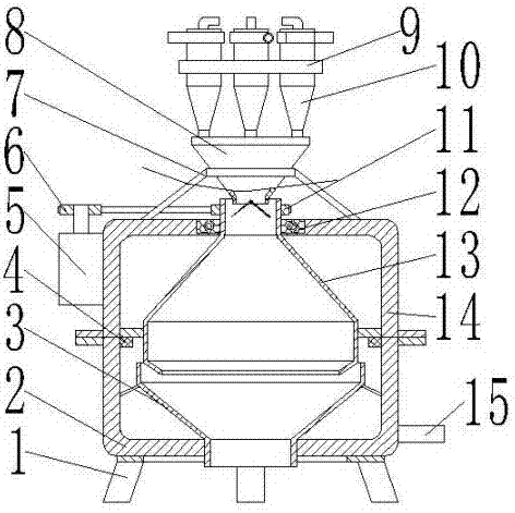
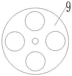
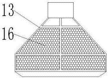
[0033] refer to Figure 1-3 , a new type of high-efficiency and energy-saving tailings dry discharge equipment, including a lower tank body 2, a No. 1 metal cylinder 13 and a No. 2 metal cylinder 3. There is a No. 1 installation hole in the middle of the outer wall of the end. The outer wall of the lower tank body 2 is welded with a drain pipe 15. The bottom of the No. 2 metal cylinder 3 is welded with a discharge head, and the discharge head is plugged into the No. 1 installation hole. The outer wall of the bottom end of No. metal cylinder 3 is welded to the inner wall of the bottom end of lower tank body 2, and the upper tank body 14 is fixed on the top of lower tank


PUM


Abstract

The invention discloses novel high-efficiency energy-saving tailing dry-discharge equipment. The equipment comprises a lower tank body, a first metal cylinder and a second metal cylinder; the bottom end of the lower tank body is fixedly provided with a metal base through bolts, a first mounting hole is formed in the middle of the outer wall of the bottom end of the lower tank body, and a drain pipe is welded to the outer wall of one side of the lower tank body; a discharging head is welded to the bottom end of the second metal cylinder, the discharging head is inserted into the first mountinghole, the outer wall of the bottom end of the second metal cylinder is welded with the inner wall of the bottom end of the lower tank body, and the top end of the lower tank body is fixedly provided with an upper tank body through bolts; and a second mounting hole is formed in the middle of the outer wall of the top end of the upper tank body, a bearing is clamped in the second mounting hole, a feeding port is welded at the top end of the first metal cylinder, the outer wall of the feeding head is clamped with the inner wall of the bearing, and the outer wall of the feeding head is fixedly provided with a first transmission disc through bolts. According to the equipment, the efficiency can be improved, the dewatering quality can be improved, the continuous operation can be realized, the energy can be saved, the dehydration rate can be improved, and the cost can be saved.

Description


Claims


Application Information

Patent Timeline
Owner 佛山市天宇鸿图创新科技有限公司
Why Eureka
Try Eureka