Planetary reducer

A technology of planetary reducer and planetary carrier, which is applied in the direction of transmission parts, gear transmission, belt/chain/gear, etc., and can solve the problems of reducer damage, uneven load distribution between planetary gears, and low positioning accuracy of internal gears. , to achieve the effect of improving reliability

Inactive Publication Date: 2018-05-18
GUANGXI LIUGONG MASCH CO LTD
View PDF8 Cites 3 Cited by
  • Summary
  • Abstract
  • Description
  • Claims
  • Application Information

AI Technical Summary

Problems solved by technology

[0005] The technical problem to be solved by the present invention is to provide a planetary reducer for the problem that the positioning accuracy of the internal gear in the existing planetary reducer is not high, and it is easy to cause

Method used


Image

  • Planetary reducer
  • Planetary reducer
  • Planetary reducer

Examples


Embodiment Construction

[0019] The specific implementation scheme is described below in conjunction with the drawings.

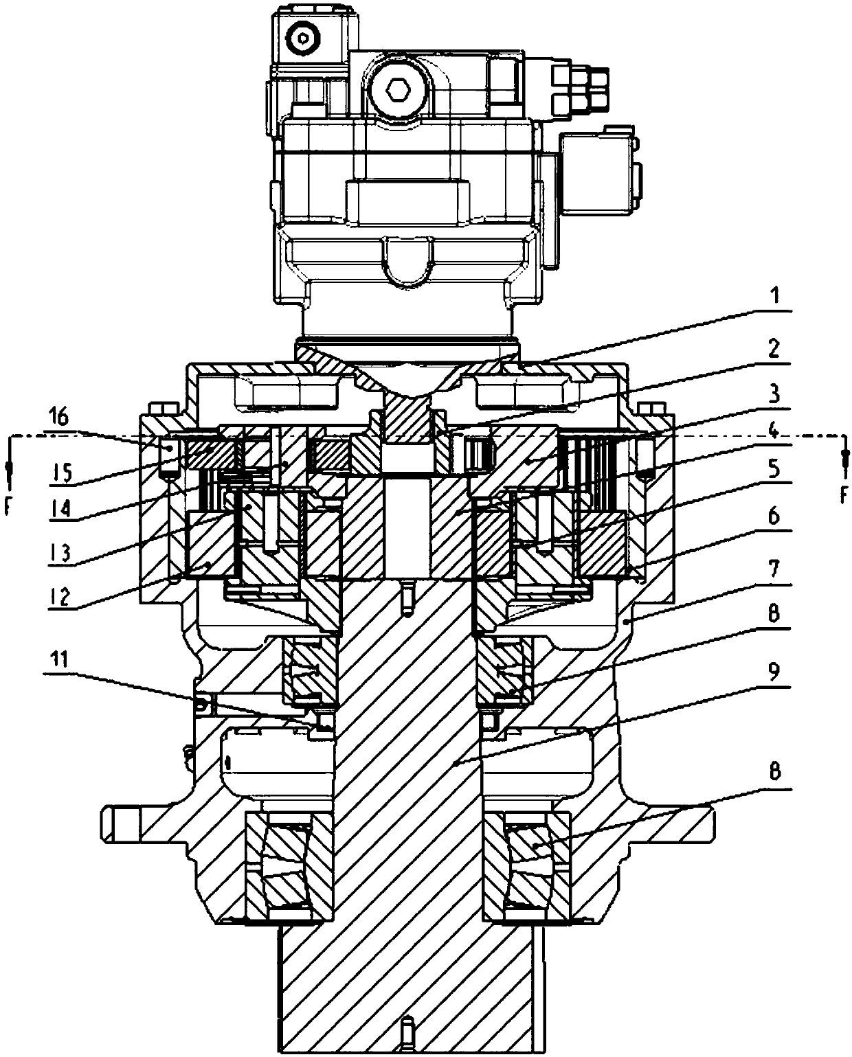
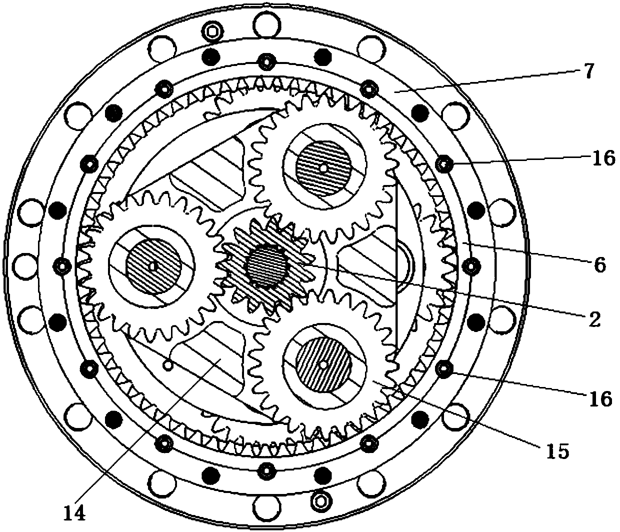
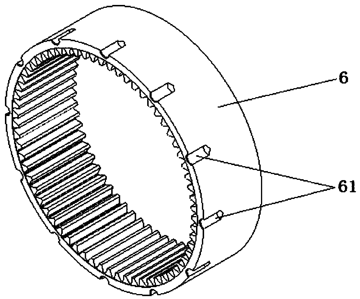
[0020] Such as figure 1 figure 2 As shown, the planetary reducer in this embodiment is a two-stage reduction planetary reducer, which is used in the slewing mechanism on an excavator, and includes a flange 1, a housing 7, a transmission gear 2, an output shaft gear 9, Internal gear 6, primary planet carrier assembly 3, secondary planet carrier assembly 5, transition gear 4 and other components. The casing 7 has circular openings at both ends, and the opening at one end is fixedly connected with the flange plate 1 by bolts. The output shaft gear 9 is installed in the casing through two pairs of spherical roller bearings 8 from the opening at the other end of the casing. Stick out. The transmission gear 2, the output shaft gear 9, the internal gear 6, the primary planet carrier assembly 3, the secondary planet carrier assembly 5, and the transition gear 4 are installed in the installatio


PUM


Abstract

The invention relates to a planetary reducer. The problems that in an existing planetary reducer, the inner gear locating precision is not high, load non-uniform distribution between planetary gears is prone to being caused, and consequently the reducer is damaged are solved. The planetary reducer comprises a flange plate, a shell, a transmission gear, an output shaft gear, an inner gear and a planetary gear assembly. Planetary gears in the planetary gear assembly are engaged with the inner gear. The inner gear is of an independent gear ring structure. The flange plate and the shell are directly and fixedly connected through a bolt. The inner gear is mounted in the shell. The inner wall face of the shell is provided with a cylindrical inner gear mounting face in clearance fit with the outer cylinder face of the inner gear. Multiple axial round pin holes distributed at intervals in the center circumferential direction are formed in the cooperation position of the outer cylinder face ofthe inner gear and the inner gear mounting face. Cylinder pins in clearance fit are mounted in the round pin holes. In the planetary reducer, when planetary gear loading is non-uniform, the inner gearand planetary gear carriers automatically float till loads between the planetary gears are distributed uniformly, and the reliability of the planetary reducer is effectively improved.

Description


Claims


Application Information

Patent Timeline
Owner GUANGXI LIUGONG MASCH CO LTD
Why Eureka
Try Eureka