Improved optical cable clamp
A technology of clamps and optical cables, applied in the direction of fiber mechanical structure, etc., to achieve the effect of reducing the size
- Summary
- Abstract
- Description
- Claims
- Application Information
AI Technical Summary
Problems solved by technology
Method used
Image

Examples
Embodiment 1
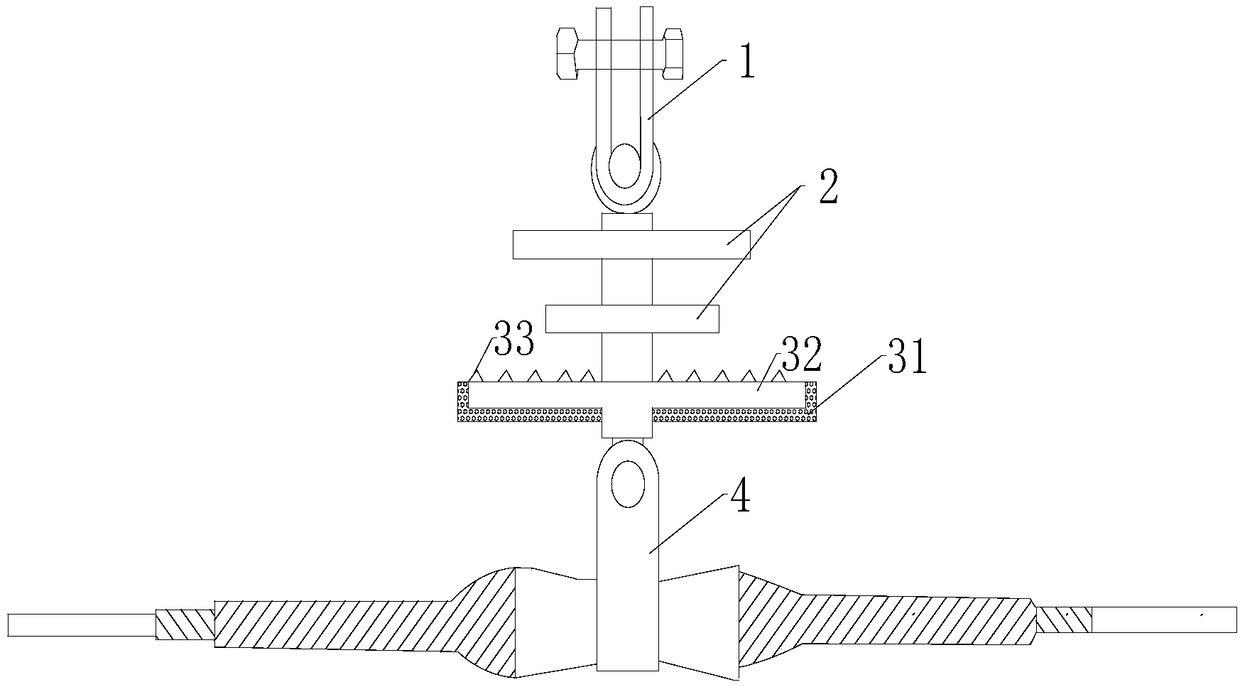
[0022] like figure 1 As shown, an improved optical cable clamp includes a U-shaped hanging ring 1, a right-angle ring is hung under the U-shaped hanging ring 1, a suspension head 4 is hung under the right-angle ring, and a discharge part is set on the right-angle ring. It includes a metal discharge layer 32 , an insulating layer 31 is provided between the metal discharge layer 32 and the suspension head 4 , and a plurality of spike protrusions 33 are provided on the upper surface of the metal discharge layer 32 .
[0023] In order to control the electrical corrosion of the ADSS optical cable, the ground leakage current can be controlled below 0.3 mA, so that a continuous arc cannot be formed, and the electrical corrosion of the ADSS optical cable will basically not occur. In the present invention, a discharge part is arranged between the ADSS optical cable and the clamp, and the ground leakage current part on the ADSS optical cable is released through the metal discharge layer 32
PUM
 Abstract
Description
Claims
Application Information
 - R&D Engineer
- R&D Manager
- IP Professional
- Industry Leading Data Capabilities
- Powerful AI technology
- Patent DNA Extraction
Browse by: Latest US Patents, China's latest patents, Technical Efficacy Thesaurus, Application Domain, Technology Topic.
© 2024 PatSnap. All rights reserved.Legal|Privacy policy|Modern Slavery Act Transparency Statement|Sitemap