Magnetic sensor for rotating electric machines

A technology of magnetic sensors and rotating electrical machines, applied in the field of magnetic sensors, can solve problems such as high cost and technical complexity, difficulty in detecting magnetic fields, and inaccurate sensor reading parameters.

Inactive Publication Date: 2018-05-22
METALROTA SRL
View PDF4 Cites 0 Cited by
  • Summary
  • Abstract
  • Description
  • Claims
  • Application Information

AI Technical Summary

Problems solved by technology

This solution implies high cost and technical complexity
[0012] Also, magnetic fields are difficult to detect due to tolerances, related to the distance of the magnet from the reader, tolerances must also be considered due to small magnetic forces, leading to inaccurate readings
[0013] Also, due to the motor gear, the shaft experiences axial displacement, causing instability in the output signal and thus inaccurate readings
[0014] Even worse, when the brake is actuated, it generates a lot of heat because the brake has to stop the motor shaft from slipping
[0015] This shortcoming leads to thermal expansion of the shaft, which translates into more tolerance issues, resulting in more inaccurate sensor readings
[0016] Therefore, the above problems lead to synchronous problems of brushless motors

Method used


Image

  • Magnetic sensor for rotating electric machines
  • Magnetic sensor for rotating electric machines
  • Magnetic sensor for rotating electric machines

Examples


Embodiment Construction

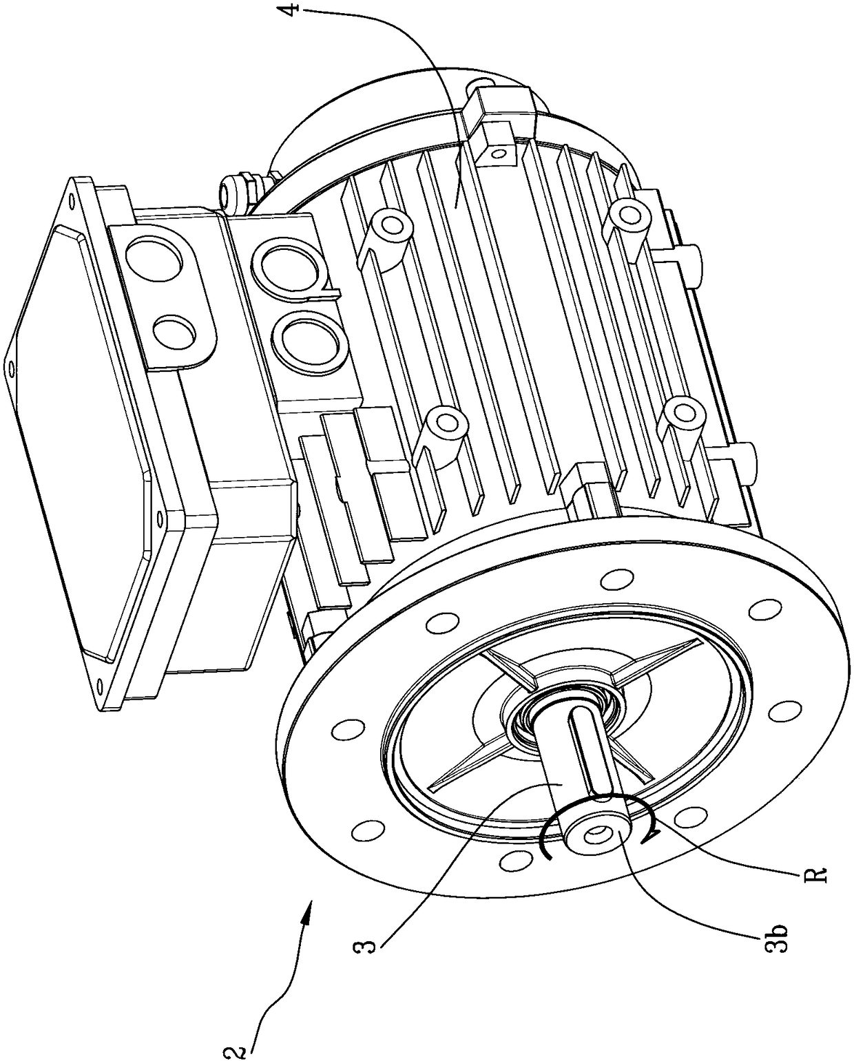
[0028] Referring to the drawings, 1 generally denotes a magnetic sensor for a rotating electrical machine 2 .

[0029] Spin Motor 2 is already in figure 1 shown in .

[0030] To illustrate the invention, the motor shaft 3 of the motor 2 and its frame 4 are shown.

[0031] The shaft 3 is configured to rotate in a rotary motion "R" and the frame 4 shown is configured to house all the components of the motor 2 which, as previously stated, are not essential to the description of the elements of the invention.

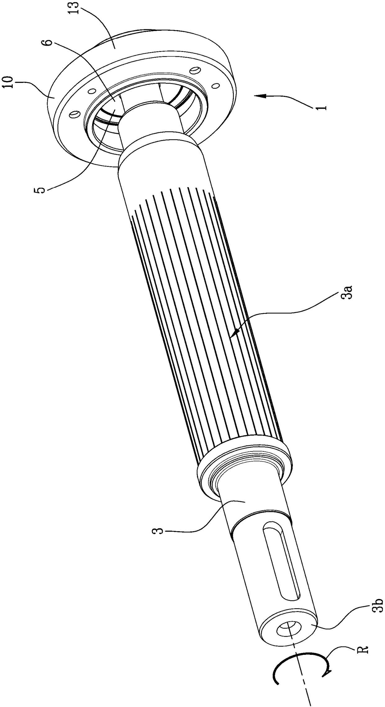
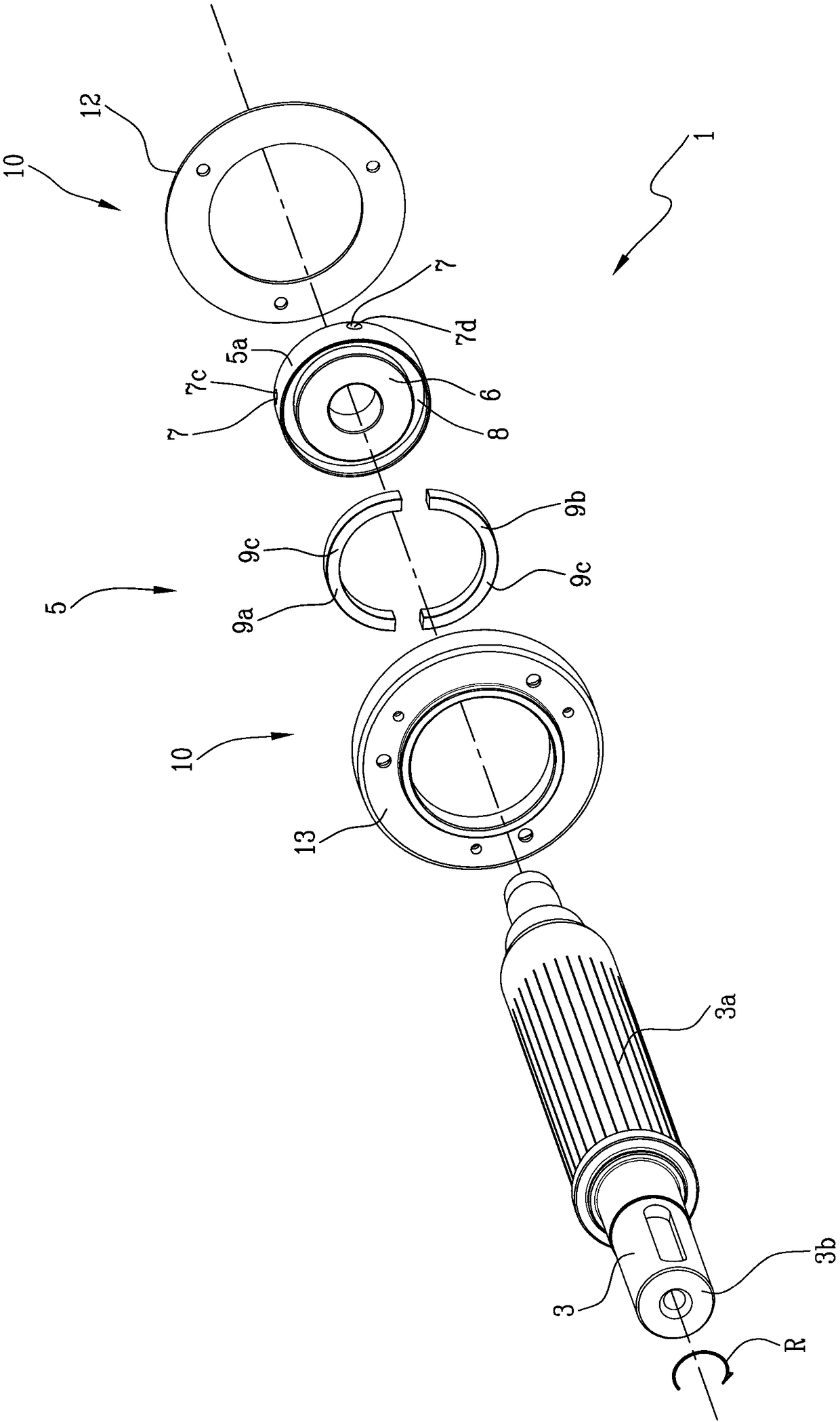
[0032] Such as figure 2 and image 3 As shown, the sensor 1 according to the invention is firmly mounted on the shaft 3 .

[0033] In particular, the sensor 1 comprises a rotating part 5 which, in use, is fixed to the side surface 3a of the shaft 3 . Preferably, the rotating part 5 of the sensor is fixed to the side surface 3 a at an intermediate point along the axis 3 . By an intermediate point is meant any point inside or outside the frame 4, preferably a point exc...


PUM


Abstract

The invention relates to a magnetic sensor (1) for rotating electric machines, adapted to be mounted solidly on a rotary shaft (3) of a rotating electric machine (2). The magnetic sensor comprises: arotary portion (5) solidly fixable to the shaft (3) in a determined axial position of the shaft (3) itself, adapted to radially produce a magnetic flux from an external lateral surface (5a) of the rotary portion (5); and a stator portion (10) adapted to be fixed to a frame (4) of the electric machine (2) and comprising a means for radially detecting variations in the magnetic flux during the rotation (R) of the shaft (3).

Description

technical field [0001] The invention relates to a magnetic sensor for a rotating electric machine, such as an electric motor. [0002] Furthermore, the invention relates to a rotating electric machine including said sensor itself. Background technique [0003] It is known that in rotating electrical machines, especially in brushless synchronous machines, it is important to synchronize the motors by means of electronic controllers. [0004] Motors of this type are used, for example, for drive wheels mounted on eg AGVs. [0005] In the case of the AGV, since the load to be transported is large, it is necessary to move at a low speed with high torque. Therefore, it is important to maintain a high torque, and the vehicle must be braked in a short space during braking by using an electric brake applied to the end of the motor shaft. [0006] Therefore, rotating electric machines requires very precise control. [0007] Currently, for control, sensors are sometimes used to retu...

Claims


Application Information

Patent Timeline
IPC IPC(8): H02K11/215H02K11/30
CPCH02K11/215H02K11/30
Inventor P·L·戴纳瑟
Owner METALROTA SRL
Why Eureka
Try Eureka