Serial communication checking and correction method

A technology of serial communication and error correction method, applied in the field of embedded use environment, can solve problems such as errors, achieve the effects of improving communication efficiency, improving the effect of checking and correcting errors, and reducing processing time

Inactive Publication Date: 2018-06-01
郑州朗睿科技有限公司
View PDF4 Cites 5 Cited by
  • Summary
  • Abstract
  • Description
  • Claims
  • Application Information

AI Technical Summary

Benefits of technology

This patented technology helps prevent mistakes when transmitting digital signals over wireless networks such as LCD displays or other electronic devices that require precise timing control between different parts within each device's circuitry. By adding an extra layer called Error Corrected Code (ECC) on top of this protocol, it becomes easier to verify if any problems are detected with these techniques compared against older methods like Cyclic Redundancy Check (CRC). Additionally, there have been improvements made to ensure efficient communication across multiple wires without interferring them due to differences in signal strength levels at specific points along their lengths. Overall, this new technique makes communication even slower and less reliable while still being effective under certain conditions.

Problems solved by technology

The technical problem addressed in this patented text relates to improving the accuracy and reliability of communications for controlling devices used at different locations on an assembly line during production operations without causing errors due to electrical noise from other sources such as power supply wires.

Method used


Image

  • Serial communication checking and correction method
  • Serial communication checking and correction method
  • Serial communication checking and correction method

Examples


Embodiment 1

[0027] Embodiment 1 Claim 1

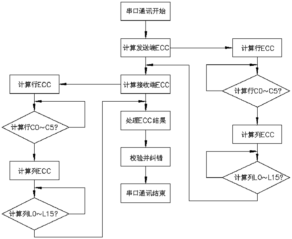
[0028] see figure 1 . The verification and error correction method of the serial port communication of the present invention adopts the ECC (Error Checking and Correction, ECC for short) verification and error correction method to realize the verification and error correction of the serial port communication, and the verification and error correction process includes:

[0029] 1) The serial port data sender saves a frame of serial port data to the sending buffer;

[0030] 2) Calculate the ECC check code of the data frame in the serial port sending buffer:

[0031] (1) Calculation column validation;

[0032] (2) Calculation row verification;

[0033] (3) Obtain the ECC check code at the sending end;

[0034] 3) The serial port data receiving end saves the received serial port data to the receiving buffer, and at the same time saves the received ECC check code of the sending end to the ECC buffer;

[0035] 4) Calculate the ECC check code of the d

Embodiment 2

[0041] see figure 1 , figure 2 , image 3 . The verification and error correction method of the serial port communication of the present invention adopts ECC verification and error correction, and the process of the verification and error correction includes:

[0042] 1. Calculate the sending end ECC:

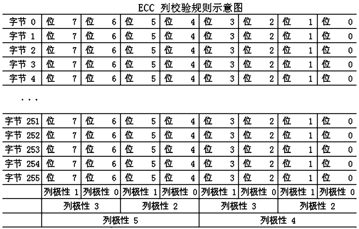
[0043] Column validation is as follows:

[0044] C0=B0^B2^B4^B6:

[0045] Indicates that the B0 bits of byte 0~byte 255 in the first column have a total of 256 bits, and then XOR with the B1 bit of the 256 bytes in the second column, and then XOR with each bit of the 4th and 6th columns. Or, in this way, C0 is actually the result of XOR of 256*4=1024 bits. Calculate C1~C5 in the same way.

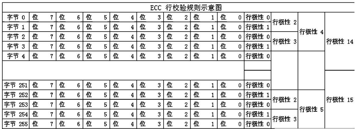
[0046] The line check is as follows:

[0047] L0=BY0(B0^B1^B2...B7)^BY2(B0^B1^B2...B7)^BY4(B0^B1^B2...B7)...BY254(B0^B1^B2...B7)

[0048] L0 is the polarity of the 0, 2, 4, 6, ... 252, 254 bytes

[0049] L1----1, 3, 5, 7...253, 255

[0050] L2----0, 1, 4, 5, 8, 9.....252, 253 (proce


PUM


Abstract

The invention relates to a serial communication checking and correction method. The serial communication checking and correction method employs an ECC (error checking and correction) mode to a serialcommunication checking and correction process and comprises: 1) saving, by a serial data transmitter, a frame of serial data to a transmitting buffer area; 2) calculating ECC codes of data frames in the serial port transmitting buffer area; 3) saving, by a serial data receiver, the received serial data to a receiving buffer area, and saving the received transmitter ECC codes to an ECC buffer area;4) calculating ECC codes of data frames in the serial port receiver buffer area; 5) subjecting the calculated transmitter ECC codes and receiver ECC codes to logic XOR operation, judging whether communication errs according to processing results, and correcting error information. The serial communication checking and correction method is particularly suitable for use in embedded service environments, especially in industrial liquid crystal displays that require transmission of mass data.

Description


Claims


Application Information

Patent Timeline
Owner 郑州朗睿科技有限公司
Why Eureka
Try Eureka