Four-shaft rotary-wing aircraft

A technology of aircraft and rotating shaft, which is applied in the aviation field, can solve the problems of poor maneuverability and maneuverability, and achieve the effect of strong maneuverability, low noise and low noise

Inactive Publication Date: 2018-06-15
NANJING UNIV OF AERONAUTICS & ASTRONAUTICS
View PDF4 Cites 5 Cited by
  • Summary
  • Abstract
  • Description
  • Claims
  • Application Information

AI Technical Summary

Benefits of technology

This patented describes different configurations for controlling movements on an airplane called a flying object (FoV). These arrangements allow for independent movement or adjustment when turning back into flight mode. They also improve their stability during takeoffs and landing phases while reducing vibrations caused by changes made over gears due to fluctuation in altitude. Additionally, these designs aim to make them more efficient without generating excessive sound levels that may affect human health.

Problems solved by technology

This patented technical problem addressed in this patent relates to developing an improved type of rotor wing or tube plane used in small drones such as those described above due to their ability to move quickly through complex terrains without being affected from turbulence caused by wind gusts during takeoff/landings.

Method used


Image

  • Four-shaft rotary-wing aircraft
  • Four-shaft rotary-wing aircraft
  • Four-shaft rotary-wing aircraft

Examples


Embodiment Construction

[0028] Below in conjunction with accompanying drawing, technical scheme of the present invention is described in further detail:

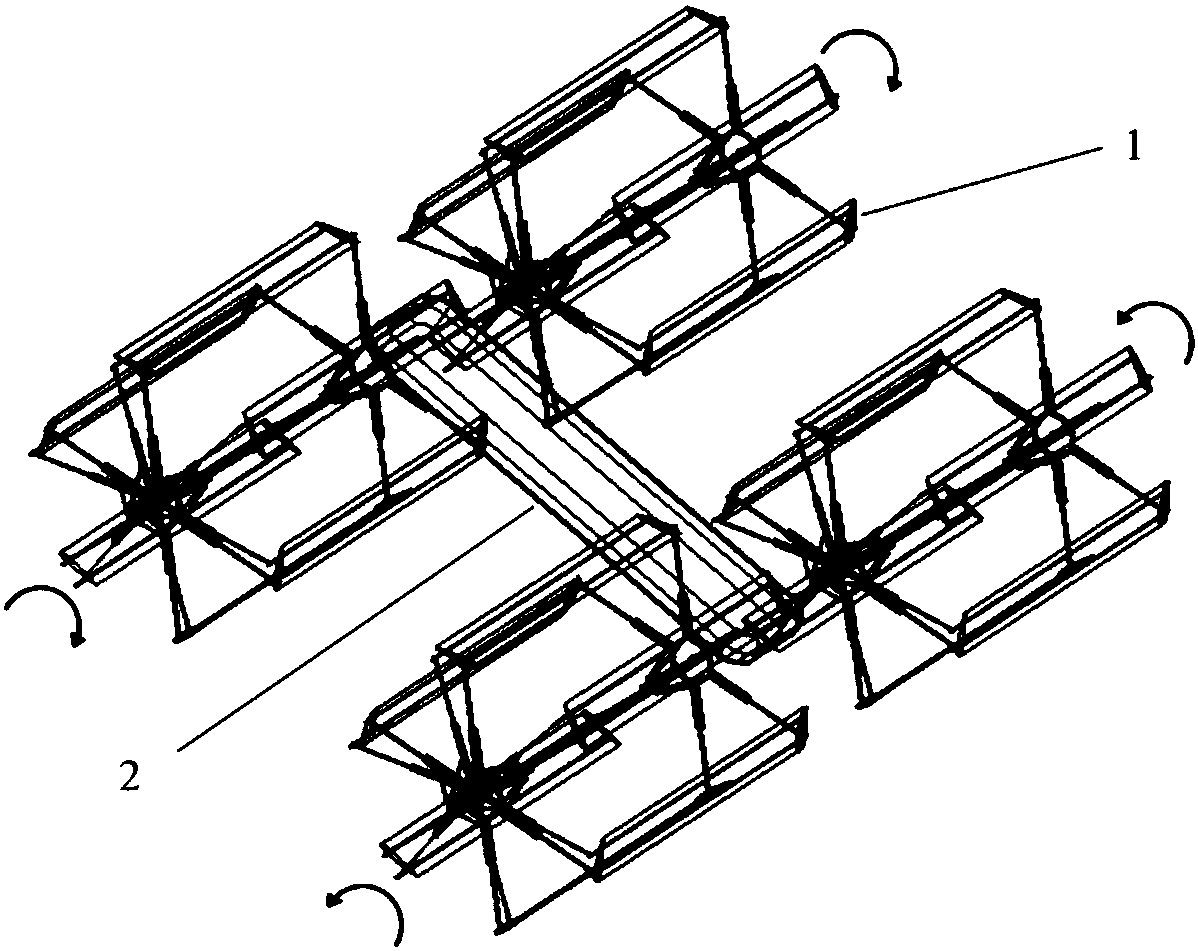
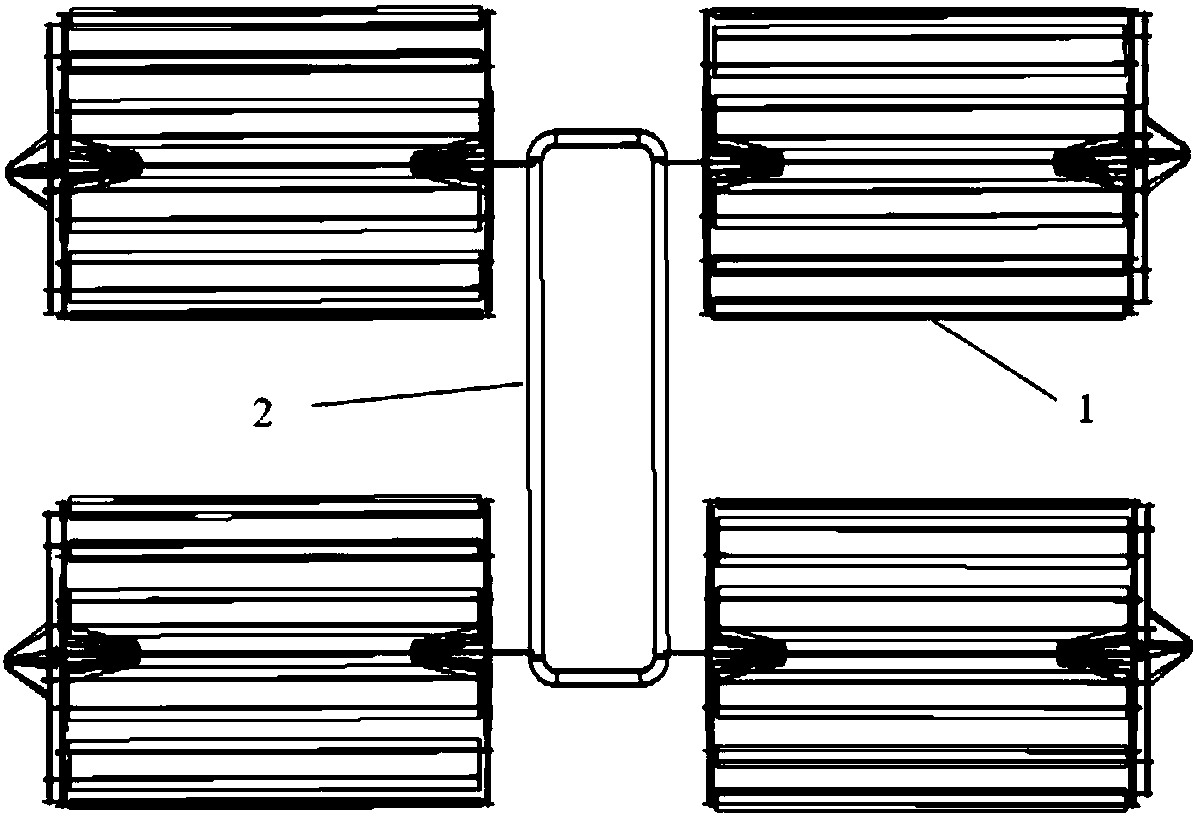
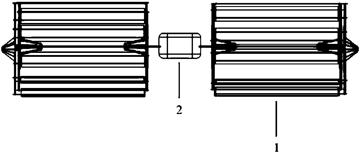
[0029] like figure 1 , figure 2 and image 3 As shown, the present invention discloses a four-axis roller aircraft, comprising four cycloidal propellers, four motors, four electronic governors, four steering gears, a control module, a fuselage and a power supply module; four pendulum The linear propellers are symmetrically distributed in pairs on both sides of the fuselage, and the center of gravity of the four-axis roller-wing aircraft is located on the same horizontal plane as the centers of the four cycloidal propellers. The direction of rotation of each cycloidal propeller is as follows figure 1 shown.

[0030] like Figure 4 , Figure 5 As shown, each of the four cycloidal paddles includes several paddles, paddle brackets and eccentric mechanisms.

[0031] The paddle bracket includes a central shaft and connecting frames at both ends of t


PUM


Abstract

The invention provides a four-shaft rotary-wing aircraft. A power device of the four-shaft rotary-wing aircraft is four symmetrically-distributed cycloidal propellers, and each cycloidal propeller isdriven by a separate motor. The rotation direction of the four cycloidal propellers is shown in the figure, and the center of gravity of the four-shaft rotary-wing aircraft is located in the same horizontal plane as the center of the four cycloidal propellers. The four-shaft rotary-wing aircraft a novel aircraft which can vertically take-off and landing and fly forward at a high speed, in addition, the four-shaft rotary-wing aircraft further has the characteristics of high efficiency, high mobility, low noise and so on.

Description


Claims


Application Information

Patent Timeline
Owner NANJING UNIV OF AERONAUTICS & ASTRONAUTICS
Why Eureka
Try Eureka