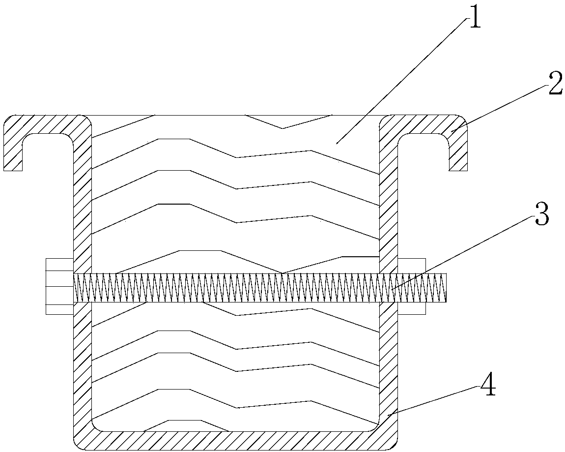
Building keel

A keel and construction technology, which is applied in the direction of construction, building structure, and on-site preparation of building components, can solve the problems of insufficient strength of wooden keels, poor fire performance, and poor corrosion resistance, etc., to reduce project costs, Large section moment of inertia, improved corrosion resistance and stability

Inactive Publication Date: 2018-06-29
天津艳丽科技有限公司
View PDF0 Cites 1 Cited by
  • Summary
  • Abstract
  • Description
  • Claims
  • Application Information

AI Technical Summary

Benefits of technology

This new type of metal brace made from laminated timber or iron sheet was developed by researchers at MIT Laboratories during World War II (MIL). It had several technical benefits that were explained earlier but they didn't meet all expectations due to its small moments of inercibility, strong load capacity, good weatherability, resistant to rustiness, stable support, easy installation, durable protection against damage caused by environmental factors such as rain water, snow, ice, heat waves, sunlight, etc., while also being cost-effective compared to traditional materials like aluminum alloys.

Problems solved by technology

This patented technical problem addressed by this patents relates to improving upon existing wood-based construction materials such as timber or steel frames used for buildings due to their weaknesses with regards to being prone to damage from rainwater during outdoor exposure over time caused by weathering (erosion) that can lead to rust on these structures. Additionally, they are costly because they require high maintenance costs compared to other alternatives like plaster boardings.

Method used


Image

  • Building keel

Examples


Embodiment Construction

[0021] It should be noted that, in the case of no conflict, the embodiments of the present invention and the features in the embodiments can be combined with each other.

[0022] In describing the present invention, it should be understood that the terms "center", "longitudinal", "transverse", "upper", "lower", "front", "rear", "left", "right", " The orientations or positional relationships indicated by "vertical", "horizontal", "top", "bottom", "inner" and "outer" are based on the orientations or positional relationships shown in the drawings, and are only for the convenience of describing the present invention and Simplified descriptions, rather than indicating or implying that the device or element referred to must have a particular orientation, be constructed and operate in a particular orientation, and thus should not be construed as limiting the invention. In addition, the terms "first", "second", etc. are used for descriptive purposes only, and should not be understood as


PUM

PropertyMeasurementUnit
Thicknessaaaaaaaaaa

Abstract

The invention provides a building keel. The building keel comprises an n-shaped galvanized steel sheets, square pillars and bolts, wherein the hollow portions of the n-shaped galvanized steel sheets are filled with the square pillars, and the bolts are used for fixing the n-shaped galvanized steel sheets and the square pillars. Flangings are arranged on the two sides of openings of the n-shaped galvanized steel sheets, bolt holes for mounting of the square pillars are further formed in the two side edges of the n-shaped galvanized steel sheets, and the n-shaped galvanized steel sheets and thesquare pillars are connected through the bolts. Water storing grooves are formed in the flangings of the n-shaped galvanized steel sheets. The adopted steel wood keel is large in section inertia, highin stress performance, moderate in price and capable of improving corrosion resistance and stability and can be widely applied; the steel-wood-integrally-combined n-shaped steel-wood keel can bring the material characteristic into play to the utmost extent and increase the strength-weight ratio; and nailing is facilitated in formwork erecting through the inlaid square pillars, meanwhile the inlaid square pillars are effectively protected through the peripheral bent n-shaped beam steel sheets, the loss of the square pillars is greatly reduced, the project cost is reduced, and environment protection is achieved.

Description


Claims


Application Information

Patent Timeline
Owner 天津艳丽科技有限公司
Why Eureka
Try Eureka