Active DFIG scheduling method based on maximal reactive power margin of wind power plant

A dispatching method and technology for wind farms, which are applied in wind power generation, electrical components, circuit devices, etc., and can solve the problems of coordinated control without considering active and reactive power, and failure to fully utilize the reactive power generation capability of DFIG.

Active Publication Date: 2018-07-10
NORTH CHINA ELECTRIC POWER UNIV (BAODING) +3
View PDF6 Cites 2 Cited by
  • Summary
  • Abstract
  • Description
  • Claims
  • Application Information

AI Technical Summary

Problems solved by technology

[0003]The traditional active power control of wind farms takes the maximum active power output of the wind farm as the control target, and the reactive power control takes the minimum voltage deviation of th

Method used


Image

  • Active DFIG scheduling method based on maximal reactive power margin of wind power plant
  • Active DFIG scheduling method based on maximal reactive power margin of wind power plant
  • Active DFIG scheduling method based on maximal reactive power margin of wind power plant

Examples


Embodiment Construction

[0029] The verification cases of the present invention will be described below in conjunction with the accompanying drawings. It should be understood that the verification cases described here are only used to illustrate and explain the present invention, and are not intended to limit the present invention.

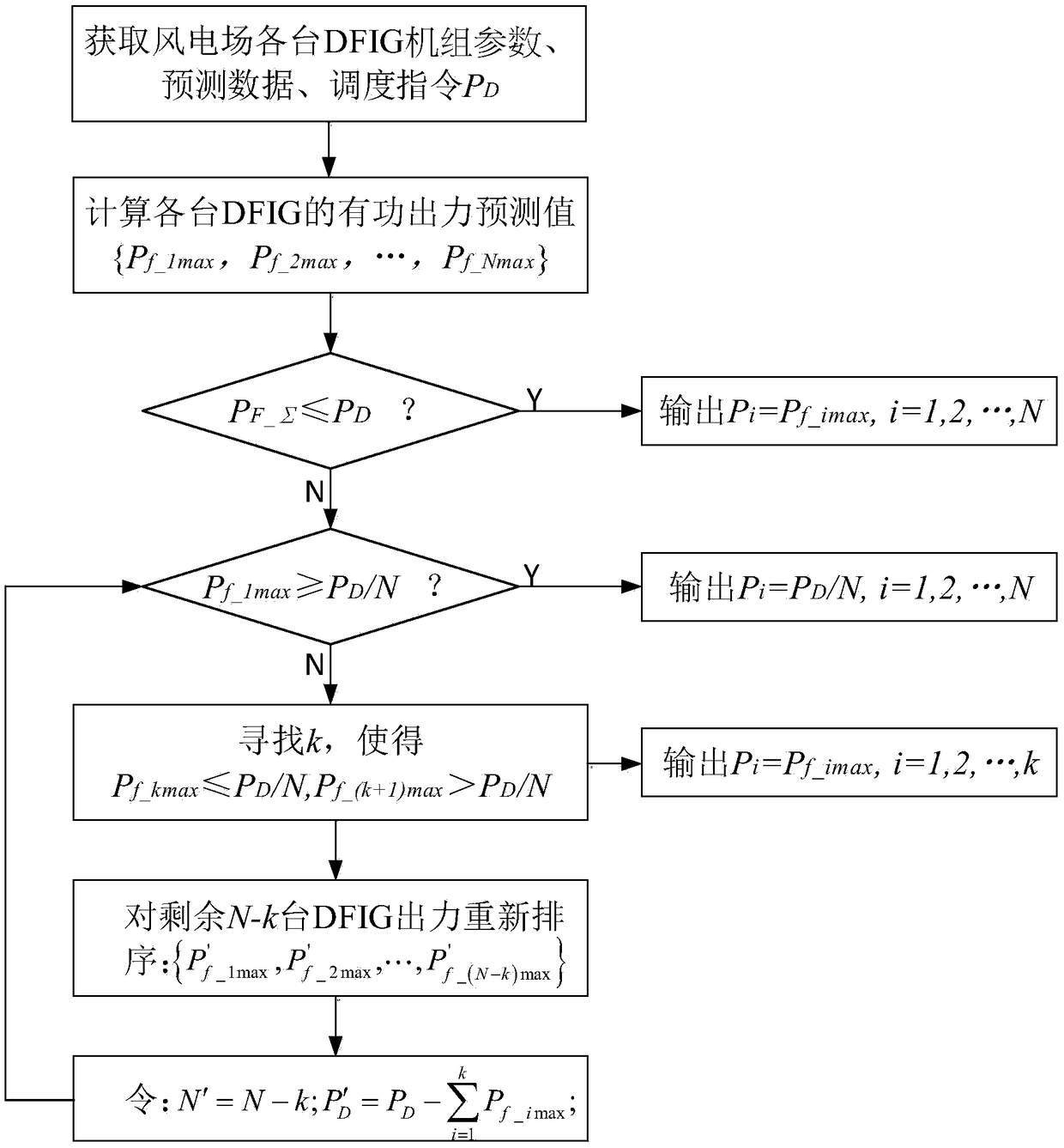
[0030] specifically, figure 1 It is a flow chart of the DFIG active power scheduling method based on the largest wind farm reactive power margin. In Figure 1, the flow chart of the scheduling method includes:

[0031] Step 1: Obtain the parameters of N DFIG units in the wind farm and the predicted value of wind speed v f ={v 1 ,v 2 ,...,v N} and the wind farm active power dispatching command P issued by the superior dispatching center D ;

[0032] Step 2: Combined with the dynamic model of the wind turbine, calculate the predicted value of the active output of each DFIG, specifically:

[0033] Step 201: According to the dynamic model of the wind turbine, calculate the


PUM


Abstract

The invention discloses an active DFIG scheduling method based on the maximal reactive power margin of a wind power plant. The method comprises that set parameters, prediction data and a scheduling instruction PD of each DFIG in the wind power plant are obtained; a predicted active output value of each DFIG is calculated by combining a dynamic model of a wind mill; upper and lower limits of reactive output of each DFIG are calculated by combining reactive output characteristic of the DFIG; when an active output predicted value PF_sigma of the wind power plant is lower than the scheduling instruction PD, each DFIG generates power according to a maximal wind energy tracking principle; and when the active output predicted value PF_sigma of the wind power plant is greater than the scheduling instruction PD, a control strategy of successive distribution is adopted to schedule and distribute the active output of each DFIG in a unified way by taking maximizing the reactive power margin of thewind power plant as a control target.

Description


Claims


Application Information

Patent Timeline
Owner NORTH CHINA ELECTRIC POWER UNIV (BAODING)
Why Eureka
Try Eureka