Rotatable optical system
A technology of an optical system and a rotating shaft, applied in optics, optical components, instruments, etc., can solve problems such as insufficient image details, and achieve the effect of expanding the scope of application
- Summary
- Abstract
- Description
- Claims
- Application Information
AI Technical Summary
Problems solved by technology
Method used
Image

Examples
Example Embodiment
[0021] Example 1
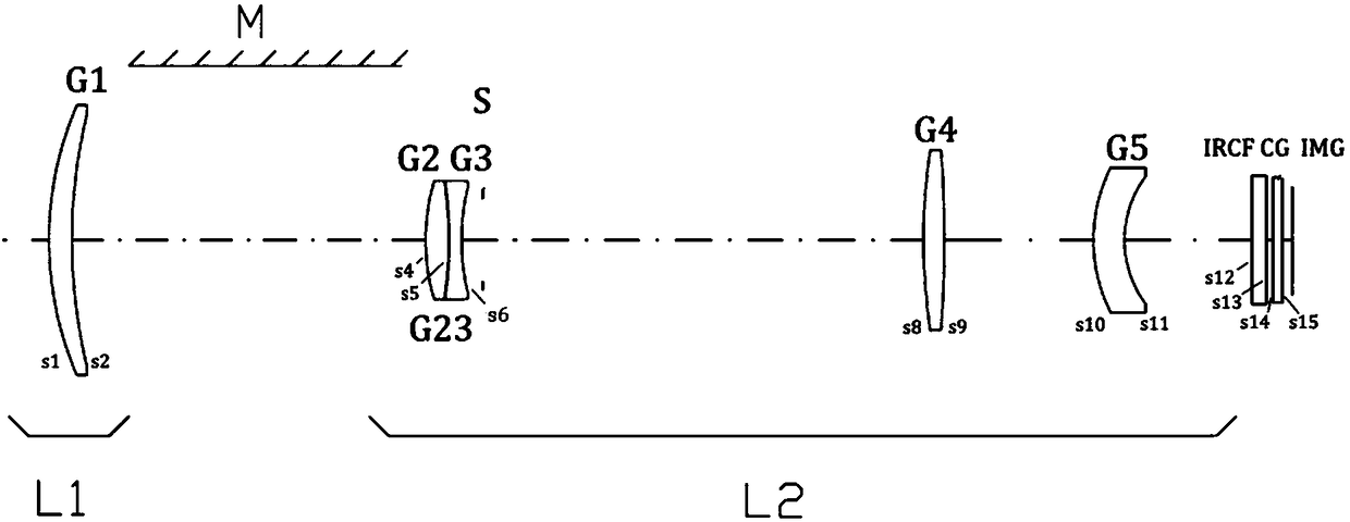
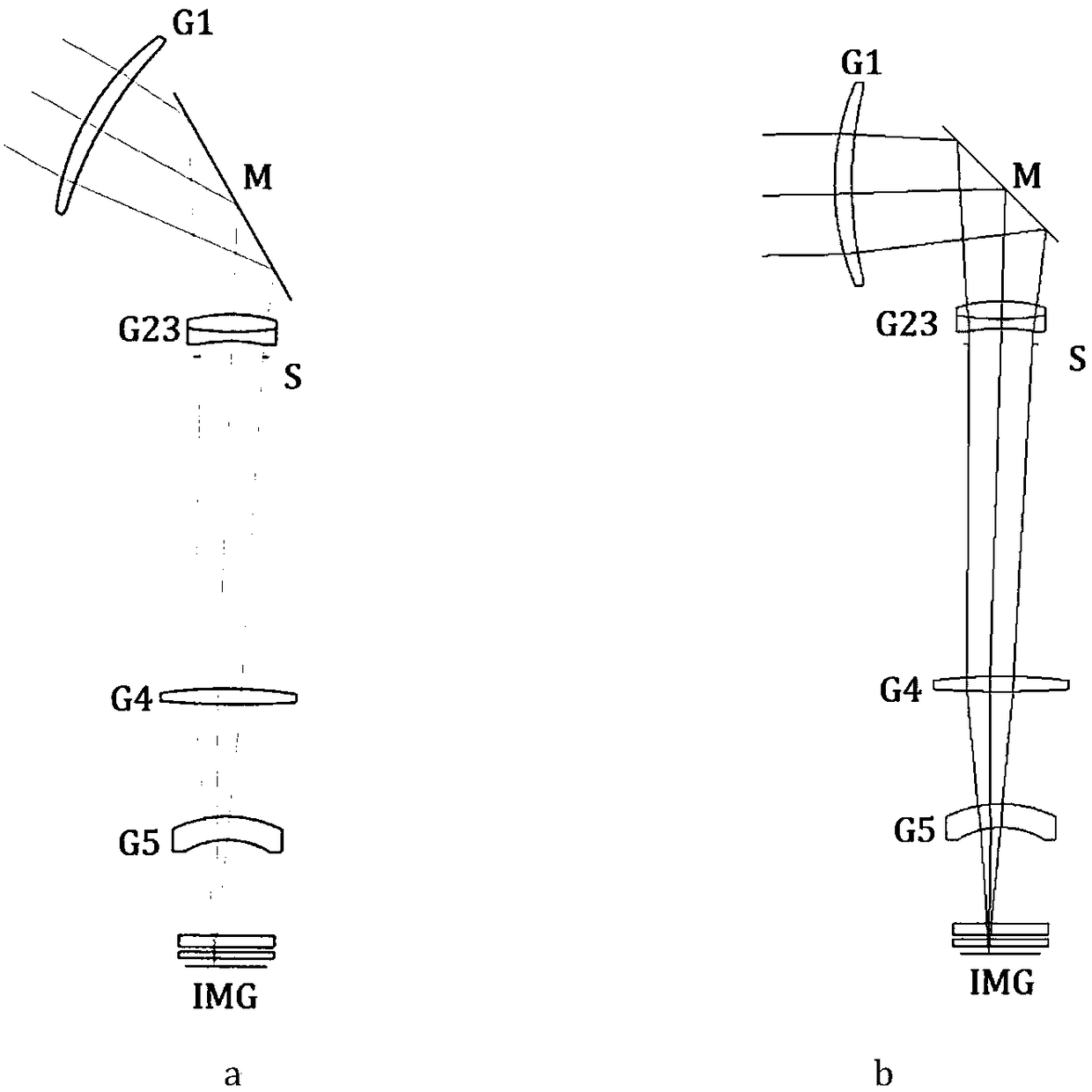
[0022] Such as figure 1 As shown, this embodiment sequentially includes from the object side to the image side: a rotatable first lens mechanism L1, a plane mirror M with two rotational degrees of freedom, a fixed second lens mechanism L2, an infrared filter IRCF , The protective glass CG and the sensor IMG, wherein: the rotation axis of the first degree of freedom rotation of the plane mirror M intersects the optical axis of the first lens mechanism L1 and is perpendicular to the light of the first lens mechanism L1 and the second lens mechanism L2 The plane formed by the axis, the second rotation axis of freedom is located in the plane of the plane mirror M, passes through the center of the plane mirror M, and is composed of the optical axis of the first lens mechanism L1 and the second lens mechanism L2 Plane.
[0023] In this embodiment, the first lens mechanism L1 includes: a spherical lens G1 with positive refractive power, and the second lens mechanism L2 in
Example Embodiment
[0031] Example 2
[0032] Such as Figure 4 with Image 6 As shown, this embodiment relates to a zoom lens, which includes in turn from the object side to the image side: a rotatable first lens mechanism L1, a plane mirror M with two rotational degrees of freedom, a second lens mechanism L2, and protection Glass CG and sensor IMG.
[0033] The first lens mechanism L1 includes: a fixed lens group Q1 and a moving lens group Q2, wherein: the fixed lens group Q1 includes a first lens G1 with negative refractive power, a second lens G2 with negative refractive power, The third lens G3 with positive power; the moving lens group Q2 includes a fourth lens G4 with positive power, a fifth lens G5 with positive power, and a sixth lens G6 with negative power, which has positive power The seventh lens G7, and the eighth lens G8 with positive refractive power.
[0034] The second lens mechanism L2 includes: a ninth lens G9 having a negative refractive power.
[0035] Table 2 shows the optical struct
PUM
 Abstract
Description
Claims
Application Information
 - R&D Engineer
- R&D Manager
- IP Professional
- Industry Leading Data Capabilities
- Powerful AI technology
- Patent DNA Extraction
Browse by: Latest US Patents, China's latest patents, Technical Efficacy Thesaurus, Application Domain, Technology Topic.
© 2024 PatSnap. All rights reserved.Legal|Privacy policy|Modern Slavery Act Transparency Statement|Sitemap