Membrane pad type solenoid valve
A technology of solenoid valve and membrane cushion, which is applied in the field of solenoid valves, can solve the problems that the membrane cushion cannot be fully opened, reduces product performance, and is easy to leak, so as to improve performance and use range, prolong service life, and increase flexibility.
- Summary
- Abstract
- Description
- Claims
- Application Information
AI Technical Summary
Benefits of technology
Problems solved by technology
Method used
Image

Examples
Embodiment 1
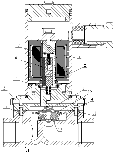
[0019] Such as figure 1 As shown, a diaphragm type solenoid valve includes a valve seat 1, a valve body 2, a moving iron core 6, a moving iron core spring 7, a guide sleeve 8, a coil 9, a diaphragm spring 10, and a diaphragm 4. The valve The body 2 is installed on the valve seat 1, the coil 9 is installed in the valve body 2, the guide sleeve 8 is set in the middle of the coil 9, the moving iron core 6 is set inside the guide sleeve 8, and the top of the moving iron core 6 passes through the moving iron core spring 7 Connect the fixed iron core of the valve body; the valve seat 1 is provided with an inlet and an outlet, and a baffle is arranged in the valve seat 1 between the inlet and the outlet, and a valve seat groove is arranged on the upper part of the baffle, and the membrane pad 4 is located in the valve seat groove , and the outer edge of the diaphragm 4 extends out of the valve seat groove, and is fixed by the valve body 2 and the valve seat 1. One end of the diaphragm s
Embodiment 2
[0021] As a preference for Embodiment 1, the valve seat 1 and the valve body 2 both contain pilot holes, and the water inlet copper column 3 is set in the pressure relief passage at the junction of the valve seat 1 and the inlet side of the valve body 2. 1 and the outlet side of the valve body 2 are provided with a water outlet copper column 11 in the pressure relief channel at the outlet side of the valve body 2, and a water discharge copper column 5 is provided in the pressure relief channel under the moving iron core 6 in the valve body 2.
[0022] Both the valve seat 1 and the valve body 2 have pilot holes inside, and the water inlet copper column 3, the water discharge copper column 5, and the water outlet copper column 11 are connected to each other to form a pilot circuit.
[0023] The bottom of the moving iron core 6 is inlaid with a polyurethane rod, which can ensure the soft contact and complete sealing when the moving iron core 6 falls into contact with the drainage cop
Embodiment 3
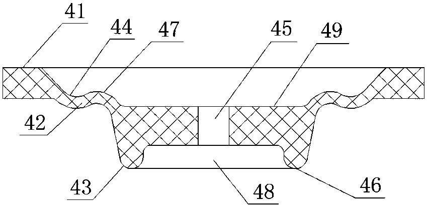
[0025] As a preference to embodiment 1, the membrane pad 4 includes a membrane pad outer ring 41, a membrane pad middle ring 42 and a membrane pad inner ring 43 connected in sequence, and the membrane pad outer ring 41 is a circular ring with a certain thickness. The membrane pad middle ring 42 includes an inner concave arc 44 from the junction of the membrane pad outer ring 41 and the membrane pad middle ring 42 to the inner ring of the membrane pad, and the inner concave arc 44 is depressed downward on the plane where the membrane pad outer ring 41 is located. , the middle part of the membrane pad inner ring 43 has a mounting hole 45, the upper part of the membrane pad inner ring 43 is connected with the membrane pad middle ring 42, and the lower part of the membrane pad inner ring 43 is provided with a raised ring 46.
[0026] There is a protruding ring 46 under the diaphragm 4, which is in close contact with the valve seat 1 under the action of water pressure, and acts as an O
PUM
 Abstract
Description
Claims
Application Information
 - R&D Engineer
- R&D Manager
- IP Professional
- Industry Leading Data Capabilities
- Powerful AI technology
- Patent DNA Extraction
Browse by: Latest US Patents, China's latest patents, Technical Efficacy Thesaurus, Application Domain, Technology Topic.
© 2024 PatSnap. All rights reserved.Legal|Privacy policy|Modern Slavery Act Transparency Statement|Sitemap