Locomotive transformer automatic exhausting apparatus, system and method
An automatic exhaust and transformer technology, applied in the direction of transformer/inductor cooling, etc., can solve the problem of human resource consumption, achieve the effect of reducing labor intensity, simple structure, and improving quality
- Summary
- Abstract
- Description
- Claims
- Application Information
AI Technical Summary
Problems solved by technology
Method used
Image

Examples
Example Embodiment
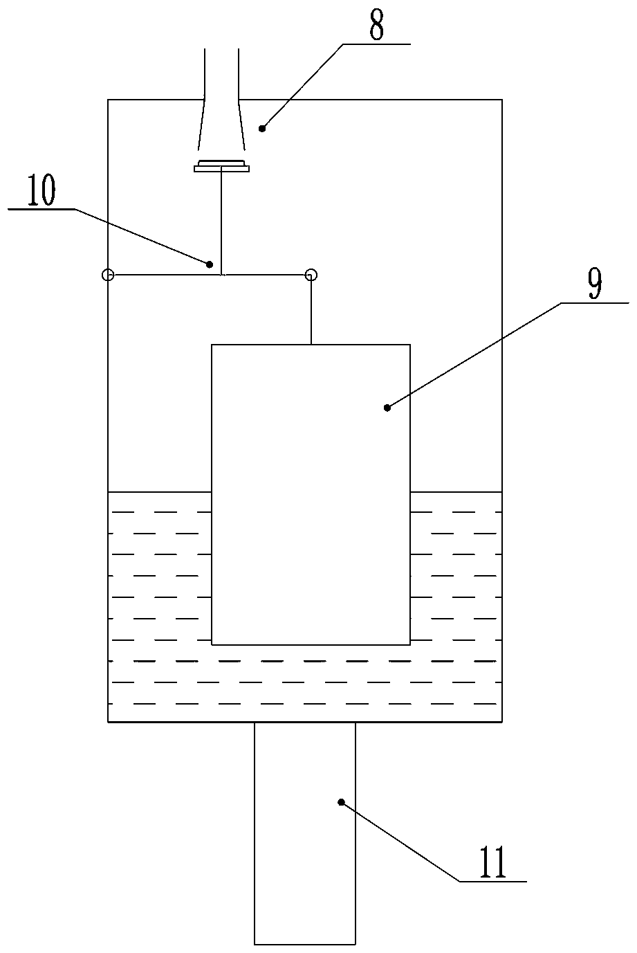
[0021] Example 1, see figure 1 As shown, an automatic exhaust device for a locomotive transformer includes a closed box provided with an exhaust cavity, a floating ball arranged in the closed box, a valve stem connected with the floating ball, and a piston connected with the valve stem; The airtight box body is provided with an exhaust hole matched with the piston; the lower part of the airtight box body is provided with an installation joint communicating with the outlet of the transformer exhaust valve. Through the floating ball installed in the closed box, the piston at the exhaust hole moves up and down to realize the automatic exhaust function.
[0022] In order to achieve a better exhaust effect, the exhaust hole is provided with an exhaust pipe that cooperates with the piston during the exhaust process, and the exhaust pipe is sealed and fixed with the closed box.
[0023] Preferably, the exhaust pipe includes a round pipe part extending outside the closed box and a tapered tub
Example Embodiment
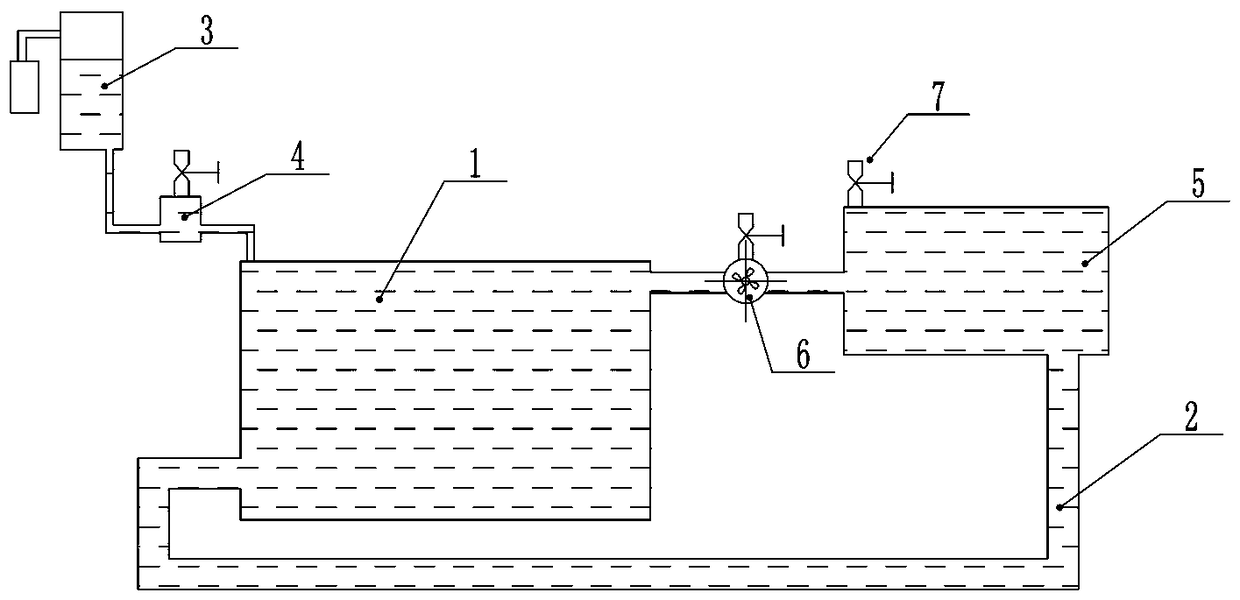
[0026] Example two, see figure 1 with 2 As shown, an automatic exhaust system for a locomotive transformer includes an exhaust valve arranged on the circulating oil circuit of the transformer. The exhaust valve is provided with an exhaust port, and the automatic exhaust system of the locomotive transformer described in Embodiment 1 is installed at the exhaust port. 气装置。 Gas device. The protection of locomotive transformer mainly includes oil flow, temperature, pressure, etc. The oil pump is set between the transformer and the radiator, another oil circulation pipeline is set between the transformer and the radiator, and the transformer exhaust valve is set on the radiator; the relay is set Between the make-up tank and the transformer, it is possible to better avoid the fault of the transformer caused by the oil circuit. The automatic exhaust device is arranged at the outlet of the transformer exhaust valve to realize the automatic exhaust of the gas in the circulating oil circuit o
PUM
 Abstract
Description
Claims
Application Information
 - R&D Engineer
- R&D Manager
- IP Professional
- Industry Leading Data Capabilities
- Powerful AI technology
- Patent DNA Extraction
Browse by: Latest US Patents, China's latest patents, Technical Efficacy Thesaurus, Application Domain, Technology Topic.
© 2024 PatSnap. All rights reserved.Legal|Privacy policy|Modern Slavery Act Transparency Statement|Sitemap