Thermal compressing machine with movable thermal compressing head

A hot press head and mobile technology, which is applied in the field of hot press machines with movable hot press head, can solve the problems of inconvenient operation, increased labor intensity of staff, and reduced work efficiency, so as to achieve improved work efficiency, novel structure, and guaranteed The effect of hot pressing quality

Pending Publication Date: 2018-11-02
江苏华驰机械有限公司
View PDF19 Cites 1 Cited by
  • Summary
  • Abstract
  • Description
  • Claims
  • Application Information

AI Technical Summary

Benefits of technology

This patented technology allows an improved mechanism for create high-quality cold pressed products with minimal damage or defects during processing. By moving the hot plungding heads over top of the table instead of relying solely upon workers' manual labor, this process becomes more efficient than traditional methods like manually holding tools while they are being worked on. Additionally, there may have been other features added such as sensors placed inside the machine itself to monitor how well it works properly without causing too much strain or injury. Overall, these technical improvements make improving production processes faster and easier.

Problems solved by technology

The technical problem addressed by this patented technology relates to improving how well an individual works with thermoformed material during production without having to adjust their location for each new part being worked upon. This makes operations more efficient while reducing the effort required from workers.

Method used


Image

  • Thermal compressing machine with movable thermal compressing head
  • Thermal compressing machine with movable thermal compressing head

Examples


Embodiment Construction

[0019] The present invention will be further explained below in conjunction with the accompanying drawings and specific embodiments. It should be understood that the following specific embodiments are only used to illustrate the present invention and are not intended to limit the scope of the present invention.

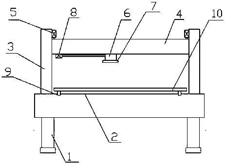
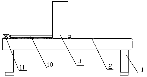
[0020] As shown in the figure, a heat press with a movable hot head according to the present invention includes a frame 1 and a controller, the upper end of the frame 1 is a workbench 2, and two Both sides are fixedly provided with column 3, and vertical chute 1 is all provided with on the opposite side of described two columns 3, is provided with pressing plate 4 between described two columns 3, and described pressing plate 4 and driving device 1 5 Transmission connection, both ends of the pressure plate 4 are slidingly arranged in the first chute, the lower end surface of the pressure plate 4 is provided with a sliding guide rail, and a thermal pressure head 6 is slidab


PUM


Abstract

The invention discloses a thermal compressing machine with a movable thermal compressing head. The thermal compressing machine comprises a machine frame and a controller, the upper end surface of themachine frame is a work platform, and vertical columns are fixedly arranged on two sides of the work platform. Vertical slide grooves I are formed in the opposite side surfaces of the two vertical columns, a pressing plate is disposed between the two vertical columns, the pressing plate is connected with a driving device I in a driving mode, and the two ends of the pressing plate are slidably arranged in the slide grooves I. A slide guide rail is arranged on the lower end surface of the pressing plate, and the thermal compressing head is slidably arranged on the slide guide rail. A heating device is fixedly arranged at the lower end of the thermal compressing head, the thermal compressing head is connected with a driving device II, and the driving device I and the driving device II are both electrically connected to the controller. The thermal compressing machine with the movable thermal compressing head has novel structure, the thermal compressing head can move left and right on the upper part of the work platform, different positions of a workpiece can be thermal pressed without adjusting the position of the workpiece, use is convenient, and the working efficiency is effectivelyimproved.

Description


Claims


Application Information

Patent Timeline
Owner 江苏华驰机械有限公司
Why Eureka
Try Eureka