Connecting clamping buckle used for photovoltaic assembly frame

A photovoltaic module and frame technology, applied in the field of photovoltaic module manufacturing, can solve problems such as water resistance that has not been effectively solved

Pending Publication Date: 2018-11-06
PERLIGHT SOLAR
View PDF0 Cites 2 Cited by
  • Summary
  • Abstract
  • Description
  • Claims
  • Application Information

AI Technical Summary

Problems solved by technology

Developing and designing a photovoltaic module that uses directly as roof tiles is a cost-saving solution to popularize photovoltaic power plants.

Method used


Image

  • Connecting clamping buckle used for photovoltaic assembly frame
  • Connecting clamping buckle used for photovoltaic assembly frame
  • Connecting clamping buckle used for photovoltaic assembly frame

Examples


Embodiment Construction

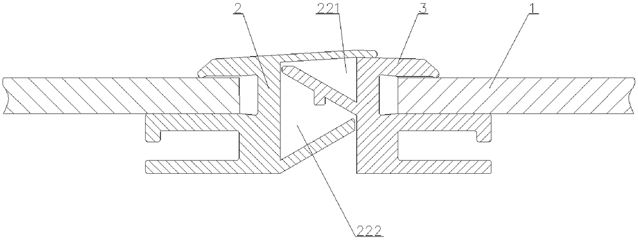
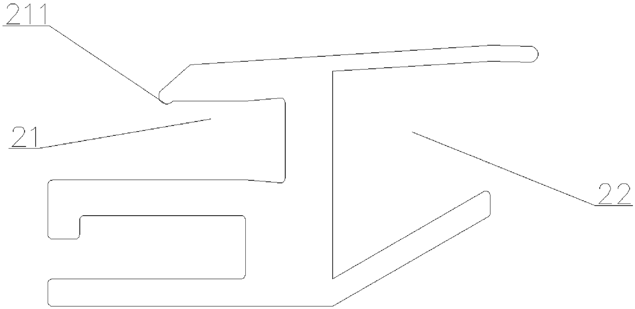
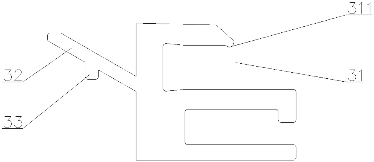
[0032] Below in conjunction with specific embodiment, content of the present invention is described in further detail, figure 1 , figure 2 , image 3 A schematic diagram of assembly in an embodiment of the connection buckle used for the photovoltaic module frame in the present invention, and a structural schematic diagram of the left and right fasteners of its constituent parts are respectively shown. like figure 1 As shown in , the connecting buckle is composed of a left engaging part 2 and a right engaging part 3 . A first photovoltaic panel placement groove 21 is opened on the left fastener 2, and a second photovoltaic panel placement groove 31 is opened on the right fastener 3. The first photovoltaic panel placement groove 21 is connected with the second photovoltaic panel The placement grooves 31 are arranged opposite to each other. A flow guiding groove 22 is also arranged on the left engaging part 2 . The bottom wall of the diversion groove 22 is inclined upwards, an


PUM


Abstract

The invention relates to a connecting clamping buckle used for a photovoltaic assembly frame. The connecting clamping buckle is composed of a left clamping fit piece and a right clamping fit piece; afirst photovoltaic panel storing groove and a second photovoltaic panel storing groove are formed in each of the left clamping fit piece and the right clamping fit piece in a back against mode, a diversion groove is further formed in the left clamping fit piece, the bottom wall of the left clamping fit piece is arranged obliquely upwards, and the top wall of the left clamping fit piece is proppedon the top wall of the right clamping fit piece; and a tilted-upward flying edge is arranged on the right clamping fit piece, inserted into the diversion groove and divides the diversion groove into afirst diversion groove and a second diversion groove, gaps are arranged between the flying edge and the top wall of the diversion groove as well as between the flying edge and the side wall of the diversion groove, and vertical-downward impermeable water edge is arranged at the bottom of the flying edge. As a result, under the normal conditions, the drainage requirements can be met only through the first diversion groove, when the drainage amount is high, the second diversion groove also plays the role, more importantly, the impermeable water edge arranged on the flying edge can make the water flow overflowed from the first diversion groove completely flow into the second diversion groove to prevent the water flow from leaking into the building.

Description


Claims


Application Information

Patent Timeline
Owner PERLIGHT SOLAR
Why Eureka
Try Eureka