Flywheel energy storage mixed type superconducting magnetic bearing

A flywheel energy storage and hybrid technology, applied in the field of magnetic bearings, can solve the problems of insufficient radial stiffness, short life, large loss, etc., and achieve the effect of suppressing radial pendulum, improving performance, and improving loss.

Active Publication Date: 2018-11-23
INST OF ELECTRICAL ENG CHINESE ACAD OF SCI
View PDF10 Cites 3 Cited by
  • Summary
  • Abstract
  • Description
  • Claims
  • Application Information

AI Technical Summary

Benefits of technology

This patented technology allows for better stabilization and reduction of unwanted movements when used with certain types of machines such as electric motors or generators. It achieves this through combining two different techniques - one uses an active controller called the rotating machine (RM) while another uses permanent magnets on either side of the motor' s axis. By adjusting both these methods based upon their respective functions they can improve the overall functioning of the device without adding extra components like relays or sensors.

Problems solved by technology

This patents describes various technical problem addressed in these inventions relating to improving the safety and durability of electric vehicles' batteries due to the lack of regulated cleanliness (GWC). Specifically, existing battery technologies like lithium ion batteries suffer from environmental concerns related to fluctuations in voltage levels during recharge cycles. To address this issue, researchers developed passive electronic insulation devices called inductively controlled pendants (IPE), which act as physical isolators without causing damage when they come close together. However, IPEs still face challenges including maintaining constant velocity and stabilized rotation under severe conditions while reducing noise emissions.

Method used


Image

  • Flywheel energy storage mixed type superconducting magnetic bearing
  • Flywheel energy storage mixed type superconducting magnetic bearing
  • Flywheel energy storage mixed type superconducting magnetic bearing

Examples


Embodiment Construction

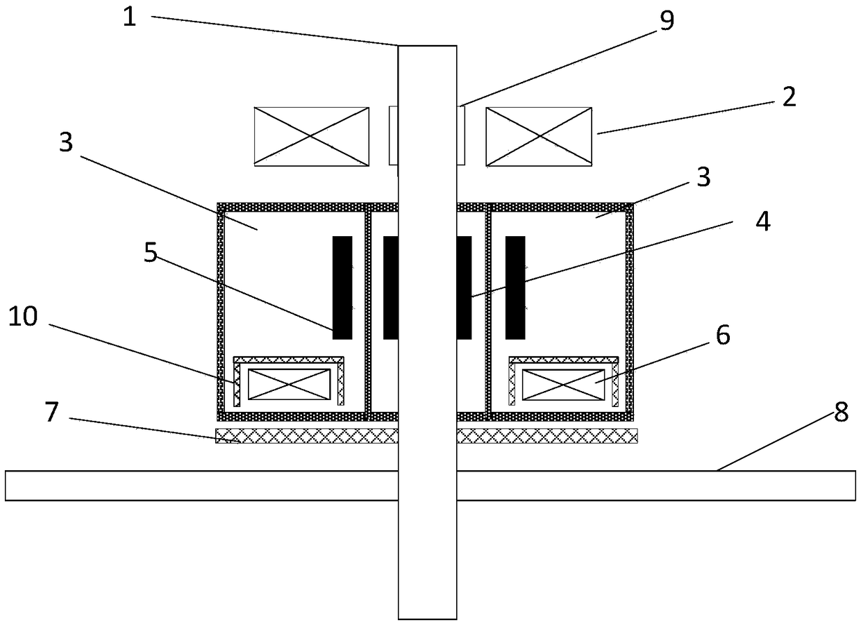
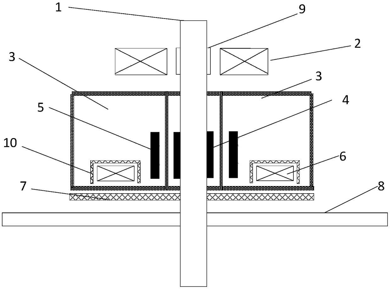
[0029] figure 1 It is a structural diagram of Embodiment 1 of the hybrid superconducting magnetic bearing for flywheel energy storage of the present invention. Such as figure 1 As shown, the hybrid superconducting magnetic bearing of the present invention consists of a stainless steel main shaft 1, a radial electromagnetic bearing stator 2, a low temperature Dewar 3, a superconducting bearing permanent magnet rotor 4, a superconducting bearing block stator 5, and a superconducting bearing coil stator 6 , superconducting bearing ferromagnetic suction disk rotor 7, flywheel 8, radial electromagnetic bearing ferromagnetic ring rotor 9, and superconducting bearing iron core yoke 10.

[0030] The radial electromagnetic bearing stator 2 is installed on the upper part of the stainless steel main shaft 1, the radial electromagnetic bearing stator 2 surrounds the radial electromagnetic bearing ferromagnetic ring rotor 9, the radial electromagnetic bearing ferromagnetic ring rotor 9 is se


PUM


Abstract

A flywheel energy storage mixed type superconducting magnetic bearing is composed of a stainless steel spindle (1), a radial electromagnetic bearing stator (2), a low-temperature Dewar (3), a superconducting bearing permanent magnetic rotor (4), a superconducting bearing block stator (5), a superconducting bearing coiling stator (6), a superconducting bearing iron magnetic suction force disk rotor(7), a flywheel (8)m a radial electromagnetic bearing iron magnetic ring rotor (9) and a superconducting bearing iron core magnetic yoke (10). The superconducting bearing block stator (5) and the superconducting bearing coiling stator (6) are arranged inside the low-temperature Dewar (3) and installed on the stainless steel spindle (1) in a sleeving mode, and liquid nitrogen or a refrigeration machine is used for cooling. The superconducting bearing coiling stator (6) is arranged below or around the superconducting bearing block stator (5). The radial electromagnetic bearing stator (2) is installed on the upper portion of the stainless steel spindle (1) in a sleeving mode. The superconducting bearing iron magnetic suction force disk rotor (7) is installed outside the low-temperature Dewar(3) and installed on the stainless steel spindle (1) in a sleeving mode.

Description


Claims


Application Information

Patent Timeline
Owner INST OF ELECTRICAL ENG CHINESE ACAD OF SCI
Why Eureka
Try Eureka