Wall type composite damper capable of improving lateral resistance performance of modularized building structure and manufacturing method

A compound damping and building structure technology, which is applied in the direction of building components, buildings, building types, etc., can solve the problem that metal dampers and viscous dampers cannot be well applied to modular building structures, and the manufacturing process of viscous dampers is complicated, Viscous fluids are prone to leakage and other problems, achieving obvious energy dissipation effects, good energy dissipation performance, and small plane size

Pending Publication Date: 2018-12-07
GUANGZHOU UNIVERSITY
View PDF5 Cites 0 Cited by
  • Summary
  • Abstract
  • Description
  • Claims
  • Application Information

AI Technical Summary

Benefits of technology

This new technology solves problems such as poor absorption/release or durability against damage caused due to external factors like impacts on buildings during construction activities. Its technical effects include improved shock resistant behavior for multiple layers without adding extra weight compared to existing methods, reduced noise levels when installed over windows, less frequent maintenance costs associated with replacing worn out parts, better energy efficiency per unit area (EPU), enhanced flexibility in design options, easy assembly process, no limitation upon opening doors and windows, simplified manufacturing processes, etc., making them suitable for use in various applications where they were previously limited in their ability to perform well.

Problems solved by technology

In this patented technical problem addressed in the patents relating to modular constructions such as homes or offices, there currently exist methods for reducing impact forces from external sources like traffic during an event but these solutions have limitations when applied to lower height architectures where vertically acting loads act over longer periods compared to older designs. There exists a new method called dynamic load systems that uses elastomer materials instead of conventional fastener assemblies. These techniques aim to provide better protection against environmental factors while still being able to accommodate different types of loading without requiring larger amounts of material.

Method used


Image

  • Wall type composite damper capable of improving lateral resistance performance of modularized building structure and manufacturing method
  • Wall type composite damper capable of improving lateral resistance performance of modularized building structure and manufacturing method
  • Wall type composite damper capable of improving lateral resistance performance of modularized building structure and manufacturing method

Examples


Embodiment 1

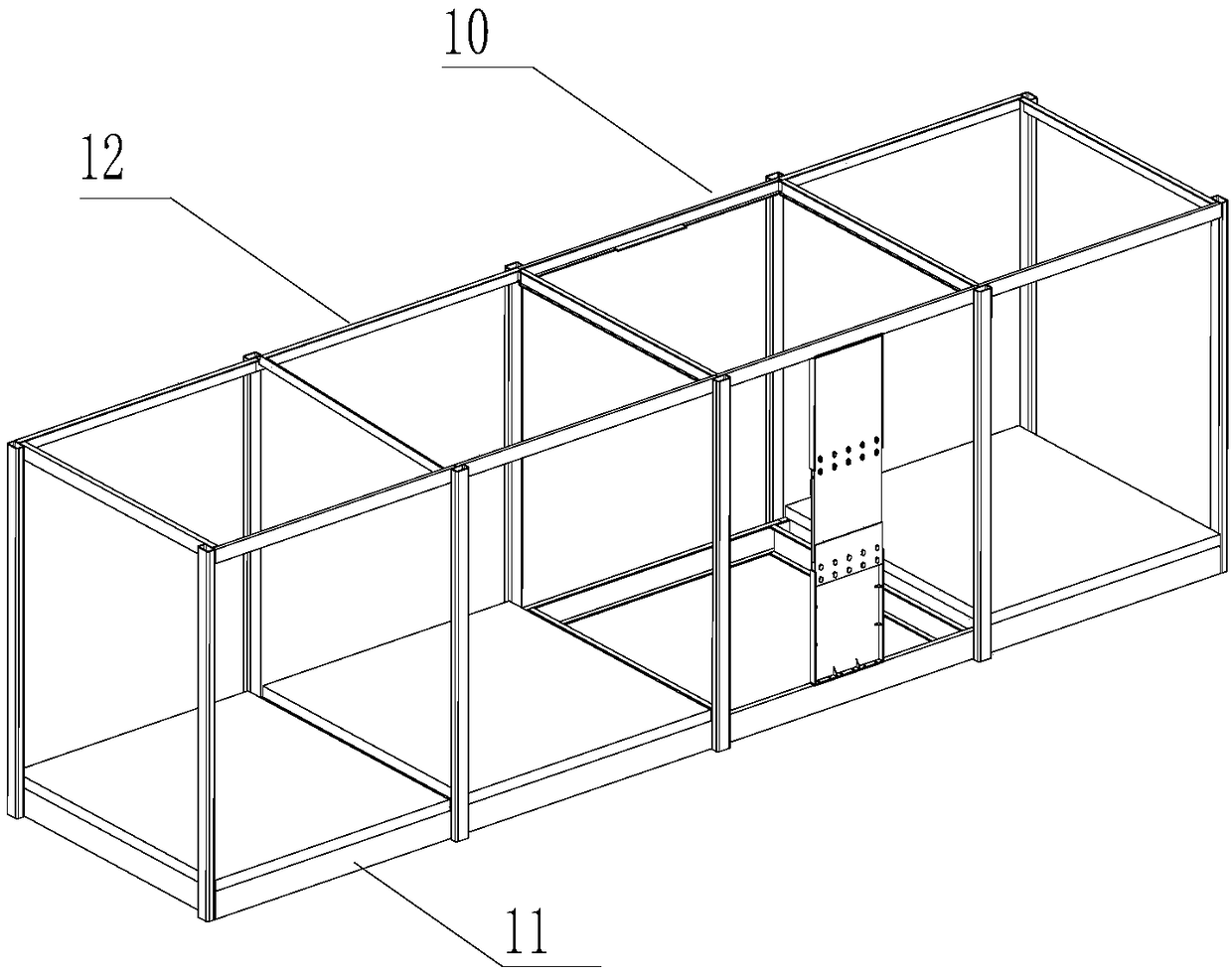
[0046] Such as figure 1 As shown, this embodiment provides a wall-type composite damper for improving the lateral resistance of a modular building structure, including an upper structure and a lower structure, wherein the upper structure is connected to the upper beam of the modular structural frame by high-strength bolts , The lower structure is connected with the module lower beam of the modular structural frame through high-strength bolts.

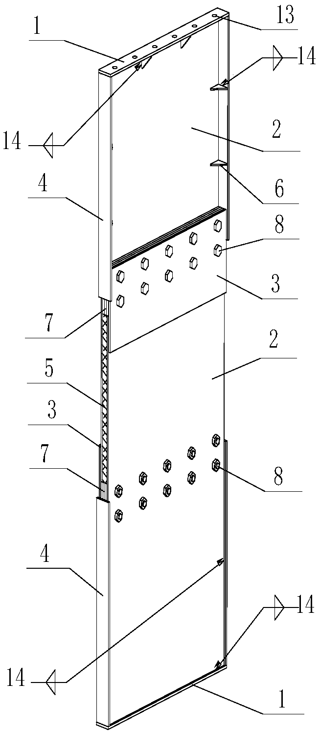
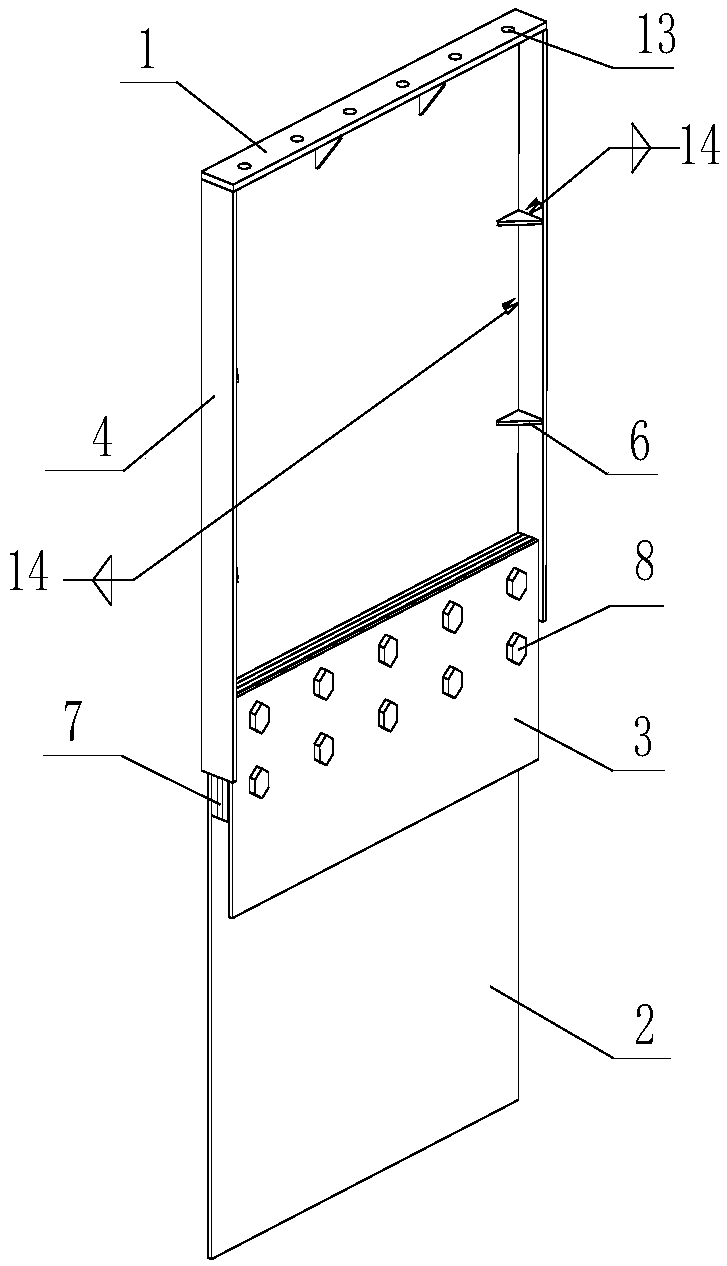
[0047] Such as Figure 2 to Figure 14 As shown, the wall composite damper includes an upper structure and a lower structure; the upper structure includes an end plate 1, a connecting plate 2, a splint 3, a copper bar 9, a rib 4, a metal gasket 7 and a stiffener 6, the upper structure and the lower The structure includes an end plate 1, a connecting plate 2, a splint 3, a rib 4, a groove 15 and a copper sheet 9; one end of the connecting plate 2 is connected to the end plate, and a splint 3 and a connecting plate 2 are arranged near the middle


PUM


Abstract

The invention relates to a wall type composite damper capable of improving lateral resistance performance of a modularized building structure and a manufacturing method. The wall type composite dampercomprises an upper structure and a lower structure; the upper structure and the lower structure comprise end plates, connecting plates, clamping plates, rib plates, grooves and copper pieces; the ends of the connecting plates are connected with the end plates, the clamping plates are arranged in the middles of the connecting plates, the connecting plates are connected with the clamping plates through high-strength bolts, the rib plates are respectively arranged on the two sides of each connecting plate, the ends of the rib plates make contact with the end plates, and the other ends of the ribplates extend to the clamping plates; the grooves are formed in the inner side surfaces of the ends of the clamping plates, and the copper pieces are arranged in the grooves and make rubbing contactwith the connecting plates; the construction of the lower structure is completely same with that of the upper structure, and the connecting plate of the lower structure is connected with the connecting plate of the upper structure. The damper is simple in structure, small in plane size, small in thickness and convenient to install, cannot be limited by holes of doors and windows, and can be widelyapplied to the multi-layer structure and the above-mentioned modularized building structure.

Description


Claims


Application Information

Patent Timeline
Owner GUANGZHOU UNIVERSITY
Why Eureka
Try Eureka