Inorganic light-emitting diode display panel and display device

A technology for light-emitting diodes and display panels, which is applied in identification devices, optics, nonlinear optics, etc., can solve the problems of high power consumption of display panels, and achieve the effect of low power consumption

Active Publication Date: 2018-12-07
SHANGHAI TIANMA MICRO ELECTRONICS CO LTD
View PDF12 Cites 0 Cited by
  • Summary
  • Abstract
  • Description
  • Claims
  • Application Information

AI Technical Summary

Benefits of technology

This technology allows an LED (Light Emission Diodes) display screen or pen to show both normal image data and written characters without requiring constant energy input. Unlike traditional displays where there are permanent changes made visible through windows, this method uses forces instead of lights to control how long it takes before displaying new ones. Additionally, unlike previous methods like cathodoluminescent lamps, these screens have reduced power usage compared to regular LCD panels.

Problems solved by technology

The invention relates to improving how much energy can be used by displaying screens while they are being written over them for writing purposes without consuming too many battery hours from their batteries.

Method used


Image

  • Inorganic light-emitting diode display panel and display device
  • Inorganic light-emitting diode display panel and display device
  • Inorganic light-emitting diode display panel and display device

Examples


Embodiment Construction

[0022] Various exemplary embodiments of the present invention will now be described in detail with reference to the accompanying drawings. It should be noted that the relative arrangements of components and steps, numerical expressions and numerical values ​​set forth in these embodiments do not limit the scope of the present invention unless specifically stated otherwise.

[0023] The following description of at least one exemplary embodiment is merely illustrative in nature and in no way taken as limiting the invention, its application or uses.

[0024] Techniques, methods and devices known to those of ordinary skill in the relevant art may not be discussed in detail, but where appropriate, such techniques, methods and devices should be considered part of the description.

[0025] In all examples shown and discussed herein, any specific values ​​should be construed as exemplary only, and not as limitations. Therefore, other instances of the exemplary embodiment may have differ


PUM


Abstract

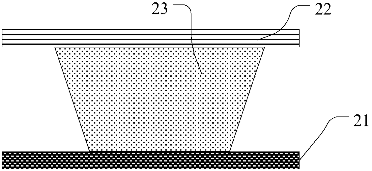
The invention discloses an inorganic light-emitting diode display panel and a display device. Display areas of the display panel comprise a plurality of light-emitting areas and non-light-emitting areas. One non-light-emitting area is arranged between at least two adjacent light-emitting areas, and the display panel comprises a first substrate, a plurality of inorganic light-emitting diodes arranged on one side of the first substrate and a stress phase change module. Each inorganic light-emitting diode comprises a first electrode, a second electrode and a p-n diode located between the first electrode and the second electrode, and the inorganic light-emitting diodes are located in the light-emitting areas. The stress phase change module comprises a third electrode, a fourth electrode and amaterial layer, the original state of the position, bearing external force, of the material layer is changed into a phase change state capable of carrying out light reflection, and when a preset electric field is arranged between the third electrode and the fourth electrode, the material layer returns to the original state from the phase change state, wherein the stress phase change module is at least located in the non-light-emitting areas. By means of the inorganic light-emitting diode display panel and the display device, the display panel can be reused as a writing pad, and the power consumption is low.

Description


Claims


Application Information

Patent Timeline
Owner SHANGHAI TIANMA MICRO ELECTRONICS CO LTD
Why Eureka
Try Eureka