Sub-nanosecond laser pulse contrast measuring device

A measuring device, laser pulse technology, applied in the direction of the instrument, can solve the problem of limited crystal size, etc., to achieve the effect of widening the starting point of the detection time

Pending Publication Date: 2018-12-21
LASER FUSION RES CENT CHINA ACAD OF ENG PHYSICS
View PDF4 Cites 3 Cited by
  • Summary
  • Abstract
  • Description
  • Claims
  • Application Information

AI Technical Summary

Problems solved by technology

Although these measurement devices have improved dynamic range, limited by crystal size, the

Method used


Image

  • Sub-nanosecond laser pulse contrast measuring device
  • Sub-nanosecond laser pulse contrast measuring device
  • Sub-nanosecond laser pulse contrast measuring device

Examples


Embodiment 1

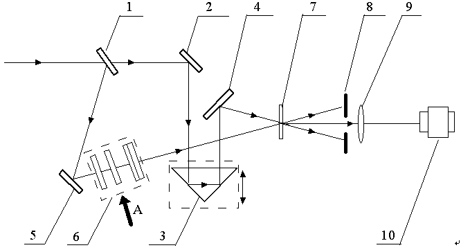
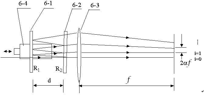
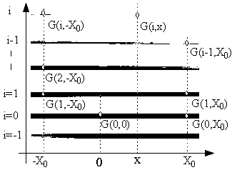
[0018] figure 1 It is a schematic diagram of the optical path of a sub-nanosecond laser pulse contrast measuring device of the present invention; figure 2 It is a schematic diagram of the optical path of the pulse delayer in the present invention, which is figure 1 A side view of the pulse delayer in ; image 3 It is a schematic diagram of the arrangement of single-shot sub-intensity autocorrelation images acquired by the CCD in the present invention; Figure 4 yes image 3 Schematic diagram of single-shot sub-intensity autocorrelation image stitching, the position of the letter in the figure indicates image 3 The start point of the mosaic position of the upper and lower adjacent images. exist Figure 1~Figure 4 Among them, in a kind of sub-nanosecond laser pulse contrast measuring device of the present invention, a beam splitter 1 is arranged on the incident direction of the high-power ultrashort laser pulse square beam, and the incident pulse light is divided into transm


PUM


Abstract

The invention discloses a sub-nanosecond laser pulse contrast measuring device. In the measuring device, a measured high-power ultra-short laser pulse square light beam is converted into reflected light and transmitted light after passing through a spectroscope, and the reflected light is changed into a series of convergent laser pulse strings with fixed time delay after passing through a pulse delay device; the laser pulse strings and transmission square light beams are simultaneously projected to frequency doubling crystals for frequency conversion so as to form a plurality of self-correlation signals which have the same spacings up and down and fixed time delays between each other after passing through the frequency doubling crystals; and finally, the mixed light passes through an imaging lens to be imaged into a CCD to be collected and processed to obtain the pulse contrast information with sub-nanosecond time recording length. The device is wide in time recording length, low in cost, simple in structure and convenient to adjust.

Description


Claims


Application Information

Patent Timeline
Owner LASER FUSION RES CENT CHINA ACAD OF ENG PHYSICS
Why Eureka
Try Eureka