Raw material mixing device for data line processing

A technology of mixing device and data line, which is applied in the direction of mixer, transportation, packaging, dissolution, etc., can solve the problems of difficult heat treatment and low work efficiency, and achieve the effect of improving work efficiency and avoiding changes

Pending Publication Date: 2019-01-11
吴江市凯宝电器有限公司
View PDF0 Cites 1 Cited by
  • Summary
  • Abstract
  • Description
  • Claims
  • Application Information

AI Technical Summary

Problems solved by technology

[0004] The purpose of this utility model is to provide a raw material mixing device for data line processing to solve the pr

Method used


Image

  • Raw material mixing device for data line processing
  • Raw material mixing device for data line processing
  • Raw material mixing device for data line processing

Examples


Example Embodiment

[0016] The following will clearly and completely describe the technical solutions in the embodiments of the present utility model with reference to the accompanying drawings in the embodiments of the present utility model. Obviously, the described embodiments are only a part of the embodiments of the present utility model, not all the embodiments. . Based on the embodiments of the present utility model, all other embodiments obtained by those of ordinary skill in the art without creative work shall fall within the protection scope of the present utility model.

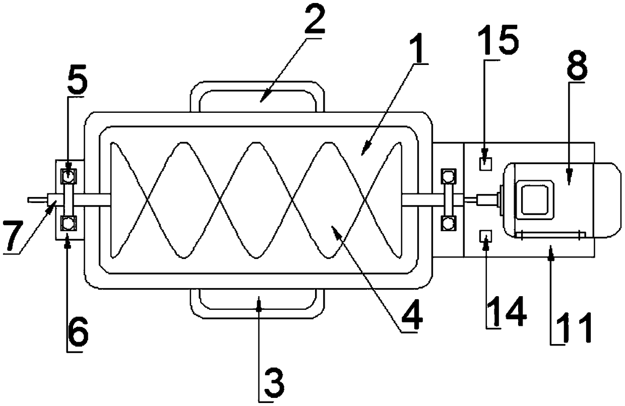
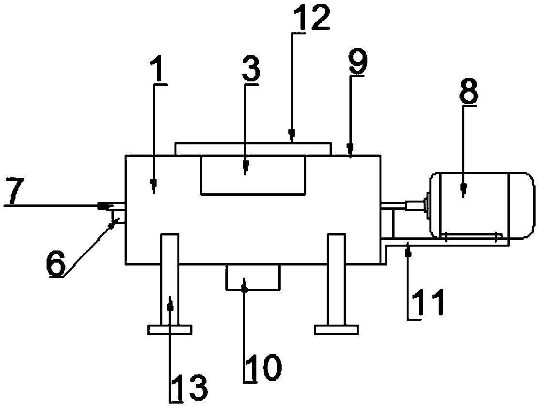
[0017] See Figure 1-3 , The utility model provides a raw material mixing device for data line processing, which includes a mixing tank 1 and a base 13. The front and back of the mixing tank 1 are respectively fixedly installed with a first feeding tank 2 and a second feeding tank 3, A rotating shaft 7 is fixedly installed inside the mixing tank 1, and the rotating shaft 7 penetrates through the tank walls on both sides of


PUM


Abstract

The invention discloses a raw material mixing device for data line processing. The device comprising a stirring tank and a base, the front side and the back side of the stirring tank are respectivelyfixedly provided with a first feeding trough and a second feeding trough, a rotating shaft is fixedly mounted in the stirring tank, rotating shaft support seats are fixedly mounted at two sides of thestirring tank, a rotating shaft limit buckle is mounted at the top end of each of the two rotating shaft support seats, an L-shaped support frame is fixedly mounted at one side of the stirring tank,a motor is fixedly mounted on the L-shaped support frame, the output end of the motor is fixedly connected with the rotating shaft, a stirring cover is mounted at the top end of the stirring tank, anda cooling fan is mounted at the top end of the stirring cover. The inner wall of each of the first feeding trough and the second feeding trough is provided with a scale, and raw materials to be mixedare directly poured to certain scale values, and are mixed, so the working efficiency is improved; and the cooling fan is arranged on the stirring cover to cool the mixed raw materials during stirring, so change of the internal structure of the raw materials, caused by high temperature, is avoided.

Description


Claims


Application Information

Patent Timeline
Owner 吴江市凯宝电器有限公司
Why Eureka
Try Eureka