High-end cleaning equipment

A clean equipment, high-end technology, applied in the field of pipe fittings processing, can solve the problems of low degree of automation, low work efficiency, high labor intensity, etc., to achieve the effect of high degree of automation, improve work efficiency, and reduce labor intensity

Inactive Publication Date: 2019-01-11
广州唐太环保科技有限公司
View PDF6 Cites 1 Cited by
  • Summary
  • Abstract
  • Description
  • Claims
  • Application Information

AI Technical Summary

Benefits of technology

This technology helps with managing pipes that are used for transportations by automatically moving them inside it without having any manual effort or tools like scrapers at all times during maintenance activities. It simplifies its design while also improving their performance over time.

Problems solved by technology

This technical problem addressed in this patented text relates to improving the automaticity and productivity of conventional pipe grinders used for machining metallic pipes during manufacturing processes due to their lack of ability to efficiently remove stubborn material from inside walls that may affect subsequent coating quality or even lead to failure issues such as leakage over time.

Method used


Image

  • High-end cleaning equipment
  • High-end cleaning equipment

Examples


Embodiment Construction

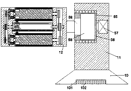
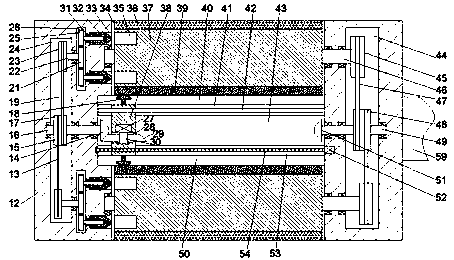
[0019] Such as Figure 1-2 As shown, a high-end cleaning equipment of the present invention includes a base 10, a support column 11 fixedly disposed above the base 10, and a cleaning sleeve 12 disposed on the left end surface of the support column 11. The sleeve 12 is provided with a first rotating cavity 34 that is symmetrical up and down and opens outward. A rotating plate 37 is rotatably provided in the first rotating cavity 34 through a first rotating shaft 46. The outer end surface of the rotating plate 37 is fixedly provided There is a sanding strip 36, the inner end surface of the rotating plate 37 is fixed with a cleaning cotton 39, the left end surface of the rotating plate 37 is symmetrically provided with a locking hole 35 opening to the left, and the left inner wall of the first rotating cavity 34 A first sliding groove 33 opposite to the locking hole 35 is symmetrically provided in the center, a locking block 32 is slidably installed in the first sliding groove 33, an


PUM


Abstract

The invention discloses high-end cleaning equipment. The high-end cleaning equipment comprises a base, a support column fixedly disposed above the base and a cleaning sleeve disposed on a left side end surface of the support column. The cleaning sleeve is internally provided with first rotating cavities which are symmetric in an up-down mode, wherein openings of the first rotating cavities face outward. Rotating plates are rotatably disposed in the first rotating cavities through first rotating shafts, grinding strips are fixedly arranged on the outer side end surfaces of the rotating plates,and two pieces of cleaning cotton are fixedly arranged on the inner side end surfaces of the rotating plates. Locking holes with openings facing left are symmetrically formed in the left side end faces of the rotating plates in an up-down mode. First sliding grooves relative to the locking holes are symmetrically formed in the inner walls of the left sides of the first rotating cavities in an up-down mode. Locking blocks are slidably installed in the first sliding grooves, and first thread holes with openings facing left are formed in the locking blocks.

Description


Claims


Application Information

Patent Timeline
Owner 广州唐太环保科技有限公司
Why Eureka
Try Eureka